


Page 3 of 4
P/N 107343 Rev D
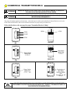
The information below indicates how to set the coding switches in the various transmitters and receivers.
I
F YOU ARE USING A
8833
OCS
-
ECONOMY OR
831
STANDARD TRANSMITTER
:
Exactly match all 8 code switches in the transmitter and receiver. The code switches
may be set in any random pattern of +, - and 0.
I
F YOU ARE USING A
8833C
OCS
-
ECONOMY OR
733
STANDARD
TRANSMITTER
:
This transmitter is used to control up to 3 different doors. This is accomplished by
setting the selector switch on the transmitter to either A, B & C and setting the #6
coding switch in the 831 receiver .
Start coding by exactly matching all 8 code switches in the transmitter and the receivers. The code switches may be set in any random
pattern of +, 0 and - positions. Next, in receiver A, set code switch #6 to the + position; In receiver B set code switch # 6 to the 0
position; In receiver C set code switch # 6 to the - position. The table to the right shows the switch positions.
I
F YOU ARE USING A
639
STANDARD TRANSMITTER
:
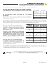
This transmitter is used to control up to 9 different doors. This is
accomplished by setting the selector switch on the transmitter to
either 1, 2, 3, 4, 5, 6, 7, 8 or 9 and setting the #7 and #8 coding
switches in the 831 receiver.
Start coding by exactly matching all 8 code switches in the
transmitter and receivers. The code switches may be set in any
random pattern of +, 0 and - positions. Next, in receiver 1, set
code switch #7 to + and code switch #8 +; In receiver 2, set code
switch #7 to + and code switch #8 to 0. Continue setting the
codes in the 831E receivers as shown in the table.
I
F YOU ARE USING A
535
STANDARD TRANSMITTER
:
This transmitter is used to control up to 27 different doors. This
is accomplished by setting the selector switches to either A, B or
C and either 1, 2, 3, 4, 5, 6, 7, 8 or 9 and setting the #6, #7 and
#8 coding switches in the 831 receiver.
Start coding by exactly matching all 8 code switches in the transmitter and receiver. Next, in receiver A1, set code switch #6 to +, set
code switch #7 to + and code switch #8 to +; In receiver A2, set code switch #6 to +, set code switch #7 to + and code switch #8 to
0. Continue setting the codes in the 831 receivers, using both tables shown above.
TRANSMITTER
A-B-C Selector
Switch Position
RECEIVER
Coding Switch
#6
A+
B 0
C-
TRANSMITTER
1 - 9 Selector
Switch Position
831 RECEIVER
Code Switch #7
831 RECEIVER
Code Switch #8
1++
2+0
3+-
40+
500
60-
7-+
8-0
9--
DISCONNECT POWER AT FUSE BOX AND DOOR OPENER BEFORE WIRING
PERMANENTLY TO PREVENT ELECTROCUTION.
WARNING
COMMERCIAL RECEIVER &
TRANSMITTER CODING INSTRUCTIONS