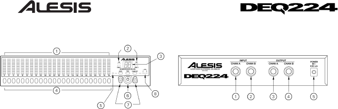
FRONT PANEL FEATURES
1. Band Gain LEDs: Indicate for each
frequency band how much cut or boost
has been applied.
2. Signal/Clip LEDs: Show audio input
levels.
3. 7-Segment Display: Shows currently
selected Program, and shows cut or
boost amount when editing a band.
4. Band Select Buttons: Press these to
select a particular band for editing.
5. Bypass LED: Indicates that the EQ is
bypassed.
6. Power Button: Turns the unit on and
off.
7. Up/Down Buttons: Change Program, or
increment or decrement Band Gain
values.
8. A/B/Link LEDs: Indicate if the current
curve display is for channel A, channel
B, or is stereo linked.
REAR PANEL FEATURES
Note: It is recommended that the DEQ224
be turned off before connecting and
disconnecting any sources to the inputs of
the unit.
1. Channel A Input: Balanced 1/4" Line Level
input to Channel A. -10dBV nominal input,
+5dBV maximum input.
2. Channel B Input: Balanced 1/4" Line Level
input to Channel B. -10dBV nominal input,
+5dBV maximum input.
3. Channel A Output: Balanced 1/4" Line
Level output from Channel A. -10dBV
nominal output, +5dBV maximum output.
4. Channel B Output: Balanced 1/4" Line
Level output from Channel B. -10dBV
nominal output, +5dBV maximum output.
5. 9VAC Power Input: 9VAC barrel jack
input. Connect only Alesis 9VAC "P3" power
supply to this jack. Connecting any other
power supply to this jack may cause
irreparable harm to the unit.


