CTH3-SERIES INSTALLATION, OPERATION AND SERVICE MANUAL
46 of 71
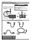
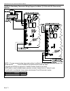
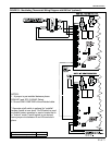
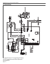
10.4.7 Cable Termination
Table lists wiring types, sizes and distances for
modulating thermostat with LonWorks
®
communication (P/N 90425104), modulating
thermostat without communication (P/N 90425105)
and BACnet
®
programmable thermostat
(P/N 90425109)
Power Requirements
Modulating thermostats require 24 volts, AC power.
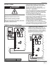
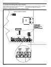
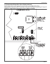
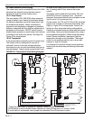
10.4.8 Remote Analog Signal
Remote Analog Signal 0-10 Vdc or 4-20mA output
from external controller or Building Management
System (BMS) directly dictates heater(s) firing rate.
An algorithm must be programmed into the BMS or
external controller to receive zone air temperature
signals from its own temperature sensors and then
deliver an output signal to the heater(s) for the
desired firing rate.
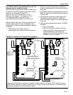
For 0-10Vdc control of the heater(s) firing rate, the
following control conditions apply:
ON/OFF relay at the external controller or BMS must
be wired to R and W terminals on the heater control
board to turn the heater ON and OFF.
Minimum rated input at 1% of signal (0-1Vdc).
Full rated input at 90% of signal (9Vdc).
Input varies linearly between 1Vdc and 9Vdc.
Table 4:
Cable Requirements
Wire Function Recommended Wire Size
(Minimum)
Specification or
Requirement
Distance (Maximum)
Digital Outputs 18 AWG (0.75 sq mm) Standard thermostat wire 1000 ft (304 m)
Modulating Outputs 18 AWG (0.75 sq mm) 1 pair 500 ft (152 m)
Outdoor Air Temperature Sensor 18 AWG (0.75 sq mm) 1 pair 500 ft (152 m)
Remote Sensor 18 to 22 AWG
(0.75 to 0.34 sq mm)
Twisted pair wire 1000 ft (304 m)
Power Wiring 18 to 14 AWG
( 0.75to 2.0 sq mm)
NEC Class II 140ºF (60°C ) Limited by line-loss effects on power
consumption.
LonWorks
®
(P/N 90424104 only)
18 AWG
(0.75 sq mm) nonshielded
1 pair Refer to E-bus Wiring Guide 74-2865
for maximum length and generic cable
specifications.
MS/TP (P/N 90425109) 18 AWG (0.75 sq mm) Shield Belden cable #82760 or equivalent Refer to Thermostat Installation Guide


