


Troubleshooting - 3
45
S1 Line Switch, Removal and Replacement
a. First remove the front panel assembly as described under “Front Panel Assembly, Removal and Replacement.”
b. Release the switch from the front panel by pressing the locking tabs inward against the body of the switch and
pushing the switch out of its opening.
NOTE: When reinstalling the switch, make sure that the letter “O” is facing up when the switch is installed
in its opening.
A3 Front Panel Board, Removal and Replacement
First remove the front panel assembly as described under, "Front Panel Assembly, Removal and Replacement."
Once you have access to the front panel board perform these steps:
a. Remove the RPG knob by pulling it away from the front panel.
b. Use a Torx T10 driver to remove the screw that secures the board to the front panel assembly.
c. Slide the board to the left to disengage the holding clips, then lift it out.
d. To reinstall the Front Panel board, perform the above steps in reverse order.
A1 Main Control Board
a. Remove the top cover and the A2 Interface board as previously described.
b. Disconnect all cables going to connectors on the main control board.
NOTE: Be sure to note the position and orientation of all cables prior to removal so that no mistake is
made later when reinstalling these cables.
c. If your power supply is equipped with a relay option board, remove the Torx T10 screw that holds the relay
board bracket.
d. Remove four Torx T15 screws that secure the main control board to the chassis.
e. Slide the main board towards the front panel to release it from chassis mounted standoffs and then lift the board
out of the chassis.
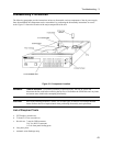
T1 Power Transformer, Removal and Replacement
To remove the power transformer, the front panel assembly must first be removed to gain access to the bracket
screws that hold the transformer in place.
a. Remove the three Torx T10 screws securing the rear of the transformer bracket to the bottom of the chassis and
the two Torx T10 screws securing the front of the transformer to the chassis.
b. Use long nose pliers to disconnect all wires going to the transformer terminals.
c. Lift the transformer out of the chassis.
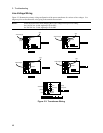
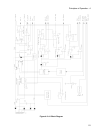
NOTE: The AC power connections at the transformer primary are line voltage dependent. Refer to Figure
3-3 subsequent reconnection.