


prewiring
• Check local building and electrical codes for compliance of the speaker wire.
• Use stranded wire of at least 16 gauge; for runs over 100 feet, it is preferable to use 14 gauge wire.
• Use only insulated staples or nylon tie straps to secure wiring within the wall to avoid shorts.
• Do not stretch the wire as it is being routed. This could create future (and costly) problems.
• Leave about 2-3 feet of free wire at both ends. Cutting excess wire is better than splicing.
• Always "home run" wires: run a continuous wire from each speaker directly to the source location.
Do not connect speakers together any other way for easier diagnosis of faulty wire or speaker problems.
• Wire speakers in phase with the same polarity. Attach positive (+/red) and negative (-/black) terminals
consistently.
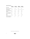
• Combined impedance for speakers connected to each channel should be at least 4 ohms. This is the
minimum impedance tolerated by most amplifiers. Check with your dealer before wiring.
preparing the wall or ceiling cutout
Confirm there is at least 1" between the final cutout and nearby studs or joints for positioning mounting
hardware. Temporarily fasten the stiff paper template (supplied) to the wall with thumbtacks. Carefully
trace around the perimeter with a pencil. Before making the final cutout of the entire hole, first make a
small 4-inch"test" cutout in the center of your penciled outline. Reach your hand inside to verify that
studs are outside the outline. This is an important step, since stud finders are not infallible.
To cut the actual hole, first score wallboard with a sharp knife; then use a keyhole saw to complete the
cut. Remove remaining debris from the edges. Hold the speaker up to the cutout to make sure it inserts
easily without forcing.
At this point, it is a good idea to secure the speaker wire to a stud near the cutout so its own weight will
not tug on the terminals of the speaker after it is connected. This will also prevent you from "losing" the
wire in the ceiling. Before attaching the wire, make sure the speaker wire runs through, not around, the
metal mounting bracket.
installation preparation
Use the supplied template to outline the mounting hole. Cut the mounting hole and remove any debris
from the area. Take the necessary steps to keep debris from falling into the back of the speaker.
Route the wires from the amplifier to the speaker installation location. Strip about 1/2" of the insulation
from the wire conductors. Twist the wire strands of the conductors into neat bundles. Insert the wires into
the provided 2-pin plug and tighten the set screws to secure the wires. Connect the speaker plug to the
matching 2-pin jack on the crossover board just before final mounting.
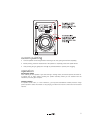
final installation
The speaker is held in place with six mounting clamps that are part of the assembly. When shipped from
the factory the clamps are pivoted so they will fit into the mounting hole. When the mounting hole clamp
screws are turned, the clamps pivot outward and are then drawn downward until they press against the
back of the mounting surface.
Insert the speaker/mounting bezel assembly into the mounting hole. Hold the speaker in place in the
mounting hole and evenly tighten the four mounting screws to draw the mounting brackets against the
backside of the mounting surface. Gradually tighten the screws, moving from one to another, until the
speaker is firmly clamped in place.
4