


8 / 0 7 • 1 0 5 1 9 3 A E
ClearGain
®
Tower-Mounted Amplifier
4
w w w . a d c . c o m • + 1 - 9 5 2 - 9 3 8 - 8 0 8 0 • 1 - 8 0 0 - 3 6 6 - 3 8 9 1
DD900 Masthead Unit Typical Specifications
ELECTRICAL SPECIFICATIONS
Nominal Impedance of RF Inputs and Outputs:
50 Ohm
Frequency Range
TX: 935 - 960 MHz or 925 - 950 MHz
RX: 890 - 915 MHz or 880 - 905 MHz
Duplex Filter Bandwidth:
25 MHz
Passband (RX)
Gain: 12 dB ±0.6 dB
Noise Figure: 1.4 dB typical; 1.9 dB maximum
Dynamic Range
Input at 1 dB Gain Compression: +1.0 dB minimum
IIP3: +15 dBm minimum
Insertion Loss of TX Path (TX to Antenna):
0.5 dB maximum
FILTER SPECIFICATIONS
Passband Return Loss
TX Band: 20 dB minimum; VSWR 1.29:1 maximum
RX Band: 20 dB minimum; VSWR 1.29:1 maximum
INTERMODULATION SPECIFICATIONS
Input Power:
2 x 20 W carriers
GSM 900 TX: -45 dBm minimum
GSM 900 RX: -116 dBm maximum
GSM 1800 RX: -98 dBm maximum
Outside Above Bands: -45 dBm minimum
Maximum Input Power at Each BTS Input
RMS Power: 200 W
Peak Power: 1.44 kW
Duration: 20 microseconds
Period Between Peaks: 550 microseconds
Peak Voltage at TX Input: 130 V
Input Power at Antenna Connector:
+16 dBm minimum
Fault Management:
Bypass
POWER SPECIFICATIONS
Operational Voltage:
7 to 15 Vdc
Operational Current:
140 mA
Alarm Current Level:
175 mA ±5 mA
PHYSICAL SPECIFICATIONS
Dimensions:
280 mm x 250 mm x 85 mm
Weight:
5.5 kg
Material:
Aluminum
Color:
Metal
ENVIRONMENTAL
Temperature Range:
-40°C to +65°C
Outdoor Protection:
IP65
QUALITY
MTBF:
180,000 hours at +25ºC
Lightning Protection
Current Peak: ±5 kA
Rise Time (10-90): 10 microseconds
Peak Half Voltage Time (50-50): 350 microseconds
Test Generator Source Impedance:
1.6 Ohm
REGULATORY
Safety:
EN60950
EMC: EN55022B
Storage: ETS3019-1-1
Transport: ETS3019-1-2
Operation: ETS3019-1-3
APPROVALS
CE
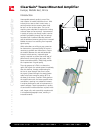
ClearGain
®
Tower-Mounted Amplifier
Europe, Middle East, Africa