


About Variable-Level Audio Outputs:
A variable-level output, such as a headphone jack or certain RCA-type outputs, provides an
audio signal that changes with the volume level set on the audio source. As the volume of the
audio source is adjusted up and down, so is the audio signal strength sent to the transmitter.
This can affect the quality of sound generated by the speaker, and may require an adjustment
of the volume level of the audio source to produce a signal strong enough for the transmitter.
Hint: On most bookshelf-type or compact stereo systems, inserting a headphone plug into
the headphone jack results in automatic cutoff of the regular, or hard-wired speakers.
Hint: Most TVs, regardless of age or price, have variable outputs. If you are unsure which
of your TV audio outputs is xed, refer to the TV instruction manual. Some TVs have
outputs that can switch between variable and xed. When given a choice, xed is always
recommended.
Troubleshooting
The following troubleshooting guide takes you through some of the more common problems
associated with the installation and/or operation of a wireless system. If the problem persists,
please call toll-free at 1-800-732-6866 or visit www.araccessories.com.
Issue: Cause and solution:
No sound • Check that the transmitter AC power adapter is fully inserted into the wall outlet and
the power cord from the AC adapter is rmly connected to the transmitter power
input jack.
• Conrm that the speaker is turned on and tuned to the transmitter—
the indicator light on the front of the speaker should be green.
• Make sure the speaker’s batteries are fresh and inserted with correct polarity (+, –).
Replace if necessary.
• Check that the audio source component (stereo, MP3 player, etc.) is turned on and
transmitting sound as it normally should.
• Make sure the volume on your audio source is turned up.
• Check that the speaker volume is turned up.
• If you are using a Tape 2 Monitor output from your receiver/amp as the audio
output, check that you have pressed the Tape Monitor/Tape 2 button on the front of
the receiver. This will turn on the Tape 2 outputs, which may not have been active.
More Helpful Information
About Fixed-Level Audio Outputs
A xed-level, or line-level, audio output is considered ideal since it provides an audio signal
unchanged by adjustments to the audio source volume control.
Hint: Fixed-level audio outputs from stereo receivers/amps will typically be designated as
Tape (or Record) outputs or DVR/DVD-R audio output connections.
Fixed-level outputs from TVs are usually marked as ‘Constant,’ ‘Fixed,’ or ‘Select.’ If they are not
marked as such, they are probably variable outputs (see “About Variable-Level Audio Outputs” on
the next page). Outputs from DVD players are almost always xed.
Hint: When connecting to the audio outputs of a DVD player, remember that the DVD player
must be showing a TV channel for sound to be produced.
Trademark(s) ® Registered www.araccessories.com MADE IN CHINA AW827 US IB 01
12 Month Limited Warranty
Specications
Transmitter
• Omni-directional 900MHz broadcast
• Effective transmitting range:
up to 150 ft. (45m)*
• Phase-locked loop circuitry (PLL)
• 3 selectable broadcast frequencies
• Stereo audio input
Speaker
• Push-button, auto-lock tuning
• 3” full-range speaker driver
• 3 Watt RMS internal amplier
• Omni-directional sound
• Frequency response: 20Hz - 20kHz
• Left/Mono/Right switch
• Operates using four (4) AA batteries (not included)
*Maximum range; results may vary according to
environment.
Audiovox Electronics Corporation (the “Company”) warrants to the original retail purchaser of this product that
should this product or any part thereof, under normal use and conditions, be proven defective in material or
workmanship within 12 months from the date of original purchase, such defect(s) will be repaired or replaced
(at the Company’s option) without charge for parts and repair labor. To obtain repair or replacement within
the terms of this Warranty, the product along with any accessories included in the original packaging is to be
delivered with proof of warranty coverage (e.g. dated bill of sale), specication of defect(s), transportation
prepaid, to the Company at the address shown below. Do not return this product to the Retailer.
This Warranty is not transferable and does not cover product purchased, serviced or used outside the United
States or Canada. The warranty does not extend to the elimination of externally generated static or noise, to
costs incurred for the installation, removal or reinstallation of the product.
The warranty does not apply to any product or part thereof which, in the opinion of the company, has suffered or
been damaged through alteration, improper installation, mishandling, misuse, neglect, accident or exposure to
moisture. This warranty does not apply to damage caused by an AC adapter not provided with the product, or by
leaving non-rechargeable batteries in the product while plugged into an AC outlet.
THE EXTENT OF THE COMPANY’S LIABILITY UNDER THIS WARRANTY IS LIMITED TO THE REPAIR OR
REPLACEMENT PROVIDED ABOVE AND, IN NO EVENT, SHALL THE COMPANY’S LIABILITY EXCEED THE
PURCHASE PRICE PAID BY PURCHASER FOR THE PRODUCT.
This Warranty is in lieu of all other express warranties or liabilities. ANY IMPLIED WARRANTIES, INCLUDING
ANY IMPLIED WARRANTY OF MERCHANTABILITY OR FITNESS FOR A PARTICULAR PURPOSE, SHALL BE
LIMITED TO DURATION OF THIS WARRANTY. ANY ACTION FOR BREACH OF ANY WARRANTY HEREUNDER,
INCLUDING ANY IMPLIED WARRANTY, MUST BE BROUGHT WITHIN A PERIOD OF 24 MONTHS FROM THE DATE
OF ORIGINAL PURCHASE. IN NO CASE SHALL THE COMPANY BE LIABLE FOR ANY CONSEQUENTIAL OR
INCIDENTAL DAMAGES WHATSOEVER. No person or representative is authorized to assume for the Company
any liability other than expressed herein in connection with the sale of this product.
Some states/provinces do not allow limitations on how long an implied warranty lasts or the exclusion or
limitation of incidental or consequential damage so the above limitations or exclusions may not apply to you.
This Warranty gives you specic legal rights and you may also have other rights which vary from state/province
to state/province.
U.S.A.:Audiovox Electronics Corp., 150 Marcus Blvd., Hauppauge, New York 11788
CANADA: Audiovox Return Center, c/o Genco, 6685 Kennedy Road, Unit #3 Door 16, Mississauga Ontario L5T
3A5
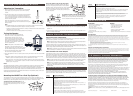
Tuning the Speaker
1. Press and hold the On/Off/Volume/Tuning
button on the front of the speaker until the
Standby/Tuned indicator turns red. This
indicator light stays red while the speaker is
tuning to the transmitter. The indicator light
turns green when the speaker is tuned to the
transmitter—you should hear sound coming
from the speaker now.
Note: If the speaker is not tuned or if the
transmitter is not connected properly, the
indicator light will stay red. If this occurs, please
see the troubleshooting section of this manual.
2. Turn the On/Off/Volume/Tuning knob to adjust
the volume on the speaker as desired.
3. Set up the speaker for mono or stereo operation using the switch on the front of the AW827
speaker.
a) Monaural operation: The monaural mode (mono) is recommended when using a single
AW827 by itself. For monaural operation, set the L/M/R switch to “Mono.”
b) Stereo operation: You need an additional AW827 speaker for the stereo option. Set the
L/M/R switch to “L” on the speaker located to the left from the listener, and set the other
speaker to the “R” position.
Notes:
The speaker automatically retunes if it loses the transmitter’s signal. You can also press the On/
Off/Volume/Tuning button on the front of the speaker to retune the speaker at any time.
The transmitter turns off automatically if there is no audio signal present for a prolonged period.
Interference in the form of static and/or distortion can sometimes be heard. If this occurs,
conrm the transmitter/speaker adjustments and indicators. If the problem persists, refer to the
Troubleshooting section of this manual.
Turning the Speaker Off
1. Press and hold the On/Off/Volume/Tuning button on the front of the speaker to turn the
speaker off.
2. Conrm that the speaker is off by verifying that the indicator light on the speaker’s front
panel is no longer illuminated.
FCC Statement
This equipment has been tested and found to comply with the limits for a Class B digital device, pursuant to part 15 of
the FCC Rules. These limits are designed to provide reasonable protection against harmful interference in a residential
installation. This equipment generates, uses, and can radiate radio frequency energy and, if not installed and used in
accordance with the instructions, may cause harmful interference to radio communication. However, there is no guarantee
that interference will not occur in a particular installation. If this equipment does cause harmful interference to radio or
television reception, which can be determined by turning the equipment off and on, the user is encouraged to try to correct
the interference by one or more of the following measures:
• Reorient or relocate the receiving antenna.
• Increase the separation between the equipment and receiver.
• Connect the equipment into an outlet on a circuit different from that to which the receiver is connected.
• Consult the dealer or an experienced radio/TV technician for help.
FCC Regulations state that unauthorized changes or modications to this equipment may void the user’s authority to
operate it.
Industry Canada Regulatory Information
Operation is subject to the following two conditions: (1) this device may not cause harmful interference and (2) this device
must accept any interference received, including interference that may cause undesired operation. The user is cautioned
that this device should be used only as specied within this manual to meet RF exposure requirements. Use of this device
in a manner inconsistent with this manual could lead to excessive RF exposure conditions.
This Class B digital apparatus complies with Canadian ICES-003.
Mounting the AW827 to a Post-Top (Optional)
This package includes a post-top mount plate that lets you safely mount the AW827 on top
of a standard 4” x 4” post. The post-top mount plate has an lock and release mechanism that
makes it easy to take the speaker off the post and put it back on whenever you want.
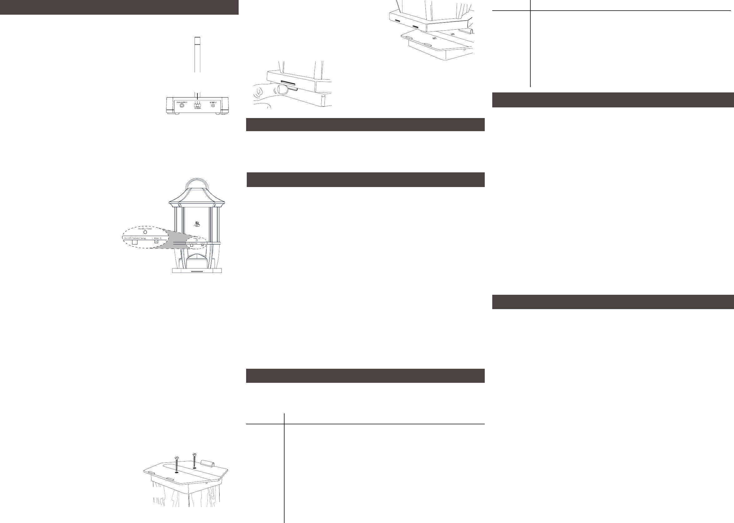
To mount the post-top mount plate: Use two
at-head wood screws (not included) to secure the
post-top mount plate to the top of a 4” x 4” post
as shown.
To lock the speaker to the post-top mount plate:
Line up the back of the speaker with the two tabs on
the back of the post-top mount plate. Tilt the speaker
backward slightly and lower the two slots on the speaker
back onto the tabs on the post-top mount plate. Push
the front of the speaker onto the post-top mount plate
to lock it into place.
Pairing the Speaker System
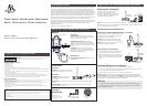
Adjusting the Transmitter
1. Turn on your audio source (for example, A/V receiver, MP3
player, stereo, etc.) and play music at a normal listening
volume.
2. Set the channel select switch on the back of the transmitter
to one of the transmitter’s three broadcast frequencies: 1,
2 or 3. If you experience poor reception or interference, try
choosing a different frequency by moving the channel select
switch to another position.
When the transmitter is receiving an audio signal and is
ready, the POWER indicator on the transmitter’s front panel
turns solid blue.
Channel
select
switch
Note
If the POWER indicator on the transmitter does not turn blue, please check the following:
- Conrm the transmitter AC power adapter is securely connected.
- Conrm the cable from the transmitter is securely connected to the audio source output
(MP3 player, A/V receiver, etc.).
- Conrm the audio source is playing audio and is turned up.
Issue: Cause and solution:
No sound/
distortion/
static
• Make sure the speaker’s batteries are fresh and inserted with correct polarity (+, –).
Replace if necessary.
• Check that the speaker’s indicator light is green.
• Change the position of the channel select switch (1, 2 or 3) to change the operating
frequency. Then press the speaker’s On/Off/Volume/Tuning button to make the
speaker retune.
• Change the location of the transmitter. Place it as high and away from obstructions
as possible. Avoid placing the transmitter directly on top of or behind a TV.
• Move the transmitter and speaker closer together. Sending the signal through
certain materials, such as glass, tile, and metal, can decrease the effective
transmitting distance of the system.
Back
To release the speaker from the post-top mount
plate: Press in on the latch on the front of the post-top
mount plate. Lift the speaker up and backward gently
until it unlatches from the post-top mount plate.
Front