


AVP700
E-34
AVP700
E-35
English
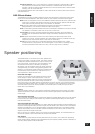
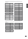
Appendix: Serial programming interface
Introduction
This section describes the remote control protocol for controlling the AVP700 via the RS232 interface.
Conventions
<
All values in this section are hexadecimal values, unless otherwise specied.
Data transfer format
<
Transfer rate: 38,400bps.
<
1 start bit, 8 data bits, 1 stop bit, no parity, no ow control.
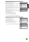
Command and response formats
Communication between the remote controller (RC) and the AVP700 takes the form of sequences of
ASCII characters, with all commands and responses having the same basic format. The AVP700 shall
always respond to a received command, but may also send messages at other times (i.e., full-duplex
communication).
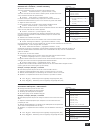
Each transmission by the RC is seven bytes long with the following format:
<STR> <CC> <P1> <P2> <ETR>
<
STR (Start transmission): 0x50, 0x43, 0x5F (“PC_”)
<
CC (Command code): the code for the command
<
Px (Parameter code): the parameters for the command
<
ETR (End transmission): 0xd
Each response by the AVP700 is eight bytes long with the following format:
<STR> <RC> <AC> <P1> <P2> <ETR>
<
STR (Start transmission): 0x41, 0x56, 0x5f (“AV_”)
<
RC (Reply code): = command code
<
AC (Answer code): answer code (see below)
<
Px (Parameter code): the parameters for the reponse
<
ETR (End transmission): 0xd
The AVP700 responds to each command from the RC within three seconds. The RC may send further
commands before a previous command response has been received.
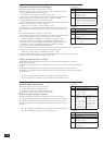
Answer codes
The following answer codes are dened:
<
Command OK – ‘P’ (0x50): The command has been accepted and processed completely.
<
Command Error – ‘R’ (0x52): An error occurred relating to the command received. This may be
either an invalid command (at this time), or a command formatting error.
State changes as a result of other inputs
It is possible that the state of the AVP700 may be changed as a result of user input via the front panel
buttons or via the IR remote control. Changes resulting from these inputs is relayed to the RC using the
appropriate message type.
For example, if the user changed the front panel display brightness using the DISPLAY button on the
front panel, a display message (dened below) would be sent to the RC. A similar action would be taken
for all other state changes (including decode mode changes).
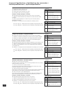
Example command and response sequence
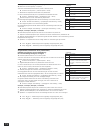
As an example, the command to be sent to bring the main zone out of stand-by (dened below) is as
follows:
STR CC P1 P2 ETR
PC_ * 1 1 (0xd)
Assuming that the command was accepted by the AVP700, the AVP700 shall respond to this command
with the following sequence:
STR RC AC P1 P2 ETR
AV_ * P 1 1 (0xd)