8 PLM Series Network Configuration Guide
5.2 PLM Series Topology
Overview
Thanks to the auto -sense and auto-uplink features of
the PLM Series’ Ethernet ports, connecting multiple
units is a simple task. A free-topology network can
be implemented easily, including external switches
or hubs as required.
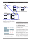
Following are some examples of various network
configurations that can be used when setting up a
PLM network.
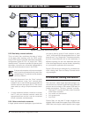
5.2.1 Daisy-chained devices
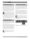
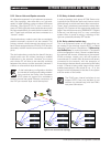
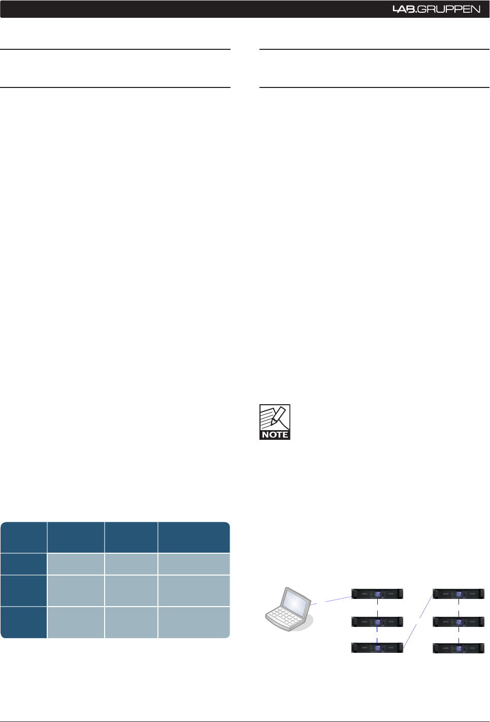
If a daisy chain network system (see figure 3) is
implemented, the secondary Ethernet connectors
on PLM Series devices can be used as “loop-thru
outputs” to send the audio and/or control signal to
the next unit in the chain (i.e. in the same rack). As an
example, a system utilizing a Dolby Lake Processor
as a “break in point” would find the DLP typically
connected to the Primary Ethernet port of the first
PLM in the rack. The signal would then travel from
the Secondary Ethernet connector of this PLM Series
unit to the Primary Ethernet connector of the next
unit in the system, and so on.
Care must be exercised in implementing a
chain topology network, as the number of
PLM Series devices being connected in this
way will have a critical bearing on network
performance parameters such as overall latency.
Also, the use of single layer cabling to connect the
network will introduce the possibility of Single Point
of Failure issues, which should be avoided at all costs
when operating critical systems Therefore, this top-
ology is NOT recommended at all for applications
using Dante and it is NOT recommended for applica-
tions with more than 10 PLMs, even when not using
Dante.
100
100
100 100
100
100
Figure 5.2.1: Daisy chain network topology
5.1 PLM Series Network
Cabling
The common cable categories used for high band-
width network connectivity are Cat-5e and Cat-6;
these are preferred choices for PLM Series network
use. However, Cat-5 may be used in limited applica-
tions, as explained below.
Cat-6, as the designation implies, is the newer
standard, and it is designed to accommodate high-
speed networks up to 250 MHz. The 10000BASE-TX
standard (using 2 pairs) requires Cat-6 cabling. Cat-6 is
fully compatible with all PLM Series network applica-
tions (including use with Dante) as it accommodates
all current Ethernet protocols.
Cat-5e (using 4 pairs) supports 1000BASE-T ap-
plications, and is also fully suited to all PLM Series
applications, including Dante.
Cat-5 cabling meets the requirements for the PLM
Ethernet control network. However, the higher ratings
of Cat-5e and Cat-6 are recommended for use as the
backbone between switches, particularly if Dante is
being used.
Cat-3 or Cat-4 cables may still be in use in some
installations. Neither of these satisfies the bandwidth
requirements of 100BASE-TX or 1000BASE-T net-
working, and should not be used with PLM Series
networks.
Table 5.1 can be used as a guide when specifying
maximum recommended lengths for Ethernet cables
within a PLM network:
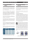
Table 5.1: Recommended PLM network cable lengths
Spectral
Bandwidth Max Length LAN
Cat-5 100 MHz 100 m 100BASE-TX
Cat-5e 100 MHz 100 m
100BASE-TX
1000BASE-T
Cat-6 250 MHz 100 m 1000BASE-TX
5 NeTwORk CONNeCTIONS aND TOPOLOgIeS


