SMC sierra monitor corporation Sentry Instruction Manual - Version 6
SERVICE
Page: 69
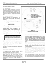
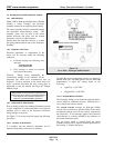
7.5 COMBUSTIBLE GAS SENSOR MODULE
(5100-02)
7.5.1 DESCRIPTION
The Combustible Gas Module includes the sensor
and electronic assembly installed in an explosion
proof housing. The sensor screws into one hub of
the enclosure and plugs into the bottom
electronics card via a six pin connector. Cabling
to the controller connects to a three pin spring
loaded terminal strip.
7.5.2 TROUBLE ANALYSIS
Electrical adjustment, or replacement of the
sensor will be necessary under the following
conditions:
• Controller displays the following error
messages:
CHK BRIDGE VOLT
SENSOR FAILURE
LOW SENSITIVITY
• False readings or alarms are received
due to sensor inaccuracy.
Warning: : During sensor adjustments the
concentration reading on the controller will be
inaccurate and alarm level concentrations may be
displayed. If false activation of the alarm relays
will cause a problem disconnect the relay wiring
prior to adjustment or turn the module off using the
CHANGE MODULE mode.
NOTE
Although all the necessary data can be collected with a
voltmeter at the sensor module, some helpful information
can be displayed or printed. See diagnostic codes 0004
and 0008 in Appendix C.
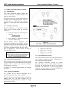
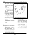
7.5.3 ADJUSTMENT PROCEDURE
Prior to reading voltages and making adjustments perform
a visual inspection to confirm that there are no physical
problems such as water in the electronics enclosure,
wiring damage or corrosion.
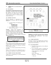
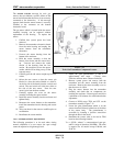
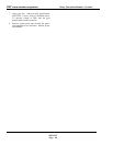
Use Figure 7-6 to locate test points during the following
procedures:
Caution: The area must be free of flammable vapors or
gases during any adjustments or maintenance procedures.
7.5.3.1 BRIDGE VOLTAGE ADJUSTMENT
Confirm that no combustible gas is present and remove
sensor module cover.
Comparing to the "GND" (ground) test point measure
"BRIDGE VOL" (bridge voltage) and adjust to 2.00 VDC
using "BRIDGE ADJ" potentiometer. Turn counter-
clockwise to increase.
7.5.3.2 ZERO ADJUSTMENT
Comparing to ground measure SIGNAL OUT and adjust to
0.18 VDC by turning
ZERO ADJ potentiometer. Turn
counter clock-wise to increase.
7.5.3.3 SPAN ADJUSTMENT
1. Determine the concentration of the calibration
gas (CG) in % LEL.
2. Use the following formula to determine the
response to the calibration gas at
SIGNAL OUT.
Voltage (Signal Out) = (CG+12)/60
For Example:
If CG = 50% L.E.L
Signal Out = (50+12)/60
= 1.03 volts
Figure 7-6
Cover Plate - Combustible Gas Module