


E-6
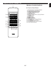
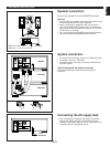
NAMES OF CONTROLS, INDICATORS AND REAR PANEL PARTS
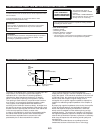
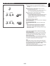
FREQUENCY STEP switch (General model only)
Because the interstation frequency spacing differs in
different areas, set the FREQUENCY STEP switch
(located at the rear) according to the frequency spacing in
your area. Before setting this switch, disconnect the AC
supply lead of this unit from the AC outlet.
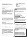
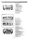
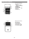
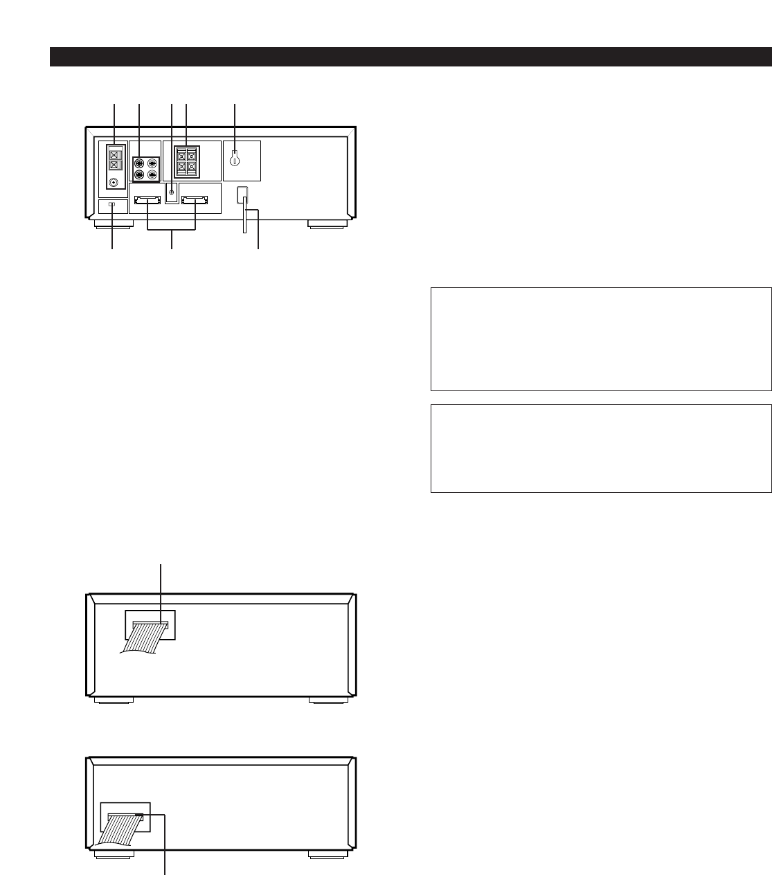
Rear Panel of Receiver
1. Antenna Terminals
2. INPUT (PHONO and AUX) Terminals
3. GND Terminal
4. SPEAKERS Terminals
5. VOLTAGE SELECTOR (General model only)
6. FREQUENCY STEP Switch (General model only)
7. System Control Sockets
8. AC Supply Lead
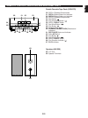
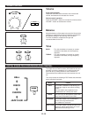
VOLTAGE SELECTOR (General model only)
The voltage selector on the rear panel of this unit must
be set for your local main voltage BEFORE plugging
into the AC main supply.
Voltages are 110/120/220/240V AC, 50/60 Hz.
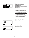
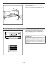
Rear Panel of Cassette Tape Deck
9. System Control Connector
Rear Panel of CD Player
10. System Control Connector
10
9
12 34 5
67 8