


1
Modules & Connecting Blocks
INSTALLATION INSTRUCTIONS
CB18
"THE STRIP-IR" PARALLEL CONNECTING BLOCK
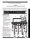
Fig. 1 The CB18
9
"VGGS"
" L+ L- R- R+ "
Label Label
VGGS
VGGS
L+ L- R- R+
L+ L- R- R+
8
1
234567
The CB18 provides a convenient way to parallel many wires onto a common 2,3 or 4 conductor bus. You
can easily connect many home run leads from multiple IR receivers to the input terminals of a Xantech
connecting block, or from Xantech 760-00 Match Maker™ room volume controls to the output terminals of
a main amplifier.
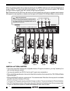
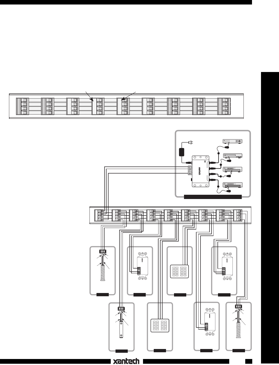
Fig. 2
+12 VDC
IR OUT
GND
780-10
J-BOX RECEIVER
+12 VDC
IR OUT
GND
780-10
J-BOX RECEIVER
+12 VDC
IR OUT
GND
780-10
J-BOX RECEIVER
CD Changer
Laser Disc
Satellite Receiver
VCR
ROOM 1, EQUIPMENT CABINET, ETC.
282M
Emitter
282M
Emitter
283M
Blink-IR™
Mouse Emitter
490-00 Series
Micro Link™
IR Receivers
3-Wire
Ribbon
Cable
IR OUT
GND
+12V
Red
Stripe
3-Wire
Ribbon
Cable
GND
+12V
480-00
Dinky Link™
IR Receiver
Red
Stripe
GND
IR OUT
+12V
780-10
J-Box
IR Receiver
GND
IR OUT
+12V
Smart Pad™
GND
IR OUT
+12V
490-00 Series
Micro Link™
IR Receivers
3-Wire
Ribbon
Cable
GND
+12V
Red
Stripe
Smart Pad™
789-44
Connecting Block
To 120 V AC
(unswitched)
782-00 Power Supply
1
2
34
56789
VGGS
VGGS
VGGS
VGGS
VGGS
VGGS
VGGS
VGGS
VGGS
283M
Blink-IR™
12VDC
+12 VDC
GND
STATUS
IR IN
EMITTERS
IR
RCVR
789-44
CONNECTING BLOCK
®
IR OUT
IR OUT
IR OUT
CB18 "THE STRIP-IR" CONNECTING BLOCK
ROOM 2
ROOM 4
ROOM 3
ROOM 5
ROOM 9
GND
+12V
780-10
J-Box
IR Receiver
GND
IR OUT
+12V
780-10
J-Box
IR Receiver
ROOM 7
ROOM 6
ROOM 8
FEATURES AND
SPECIFICATIONS
• Nine 4-terminal plug-in connec-
tors on a 4-conductor bus.
• One-in eight-out or eight-in one-
out capability.
• Adhesive backed labels are in-
cluded for attachment to the plug-
in terminals so that IR or speaker
lead connections can be easily
identified.
• High current design allows ampli-
fiers rated as high as 500 watts to
be used with the CB18.
• Screw terminals handle wire sizes
from 24 to 12 gauge.
• Dimensions: 11 1/4" x 1-1/4" x 1-
1/4".
INSTALLATION
When connecting an IR receiver/
keypad system, begin by placing
the "VGGS" labels on each of the
terminal plugs as shown in Fig. 2 .
"V" stands for +12 Volts, "G" for
Gnd and "S" for Signal (IR OUT).
This will aid you in keeping track of
your connections.
Fig. 2 illustrates how the CB18 may
be used to connect 8 home runs
from IR receivers and keypads to
the input terminals of a 789-44 Con-
necting Block in a 9-room system.