


IR Receivers & Modems
1
INSTALLATION INSTRUCTIONS
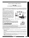
The 291-80 is a small shelf-top infrared repeater assembly. It is a CFL (compact fluorescent light) friendly
version of the 291 Hidden Link series. It is specifically designed to have great immunity to CFL type infrared
interference and to have exceptional IR reception range. In addition, the 291-80 will operate in direct
sunlight!
The 291-80 is equipped with a 7-foot cable and 3.5
mm stereo mini plug, which is plugged directly into
the "IR RCVR" jack on the CB12 (included). It can
also be plugged into the "AUX" or "IR RCVR" jack
on other Xantech connecting blocks, such as mod-
els 789-44, CB-60 and 791-44. The mini plug
provides quick installation where the connecting
block is within reach of the 7-foot cable — as when
installing the 291-80 in a cabinet where the con-
trolled equipment is behind closed doors. How-
ever, the cable length can be easily increased to
accommodate any desired application. See Fig. 4.
INSTALLATION
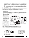
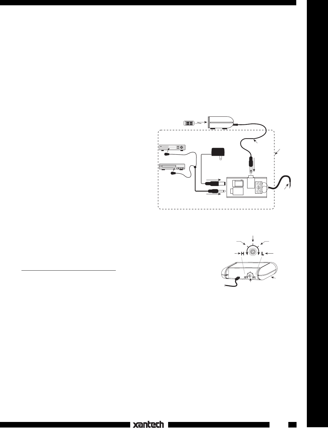
A typical system is shown in Fig. 1. Refer to this
diagram when making connections:
In this system a 286M Dual Blink-IR Emitter is shown connected to the
"OUT" jack. A single emitter could also be used, such as the model
282M or 283M. If expansion beyond two emitters is required, use a
Xantech 789-44, CB-60 or 791-44 Connecting Block in place of the
CB12.
Do not use the CB12 in this case.
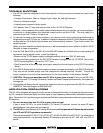
Adjusting the IR Carrier Frequency
The 291-80 is factory set to an IR carrier repeat frequency of 38 kHz.
This will be correct for the majority of installations. However, some
manufacturer's components that you wish to control may use different
carrier frequencies (such as the RCA DSS receivers that use 56 kHz). If such carrier frequencies fall within
the range of 32 kHz to 56 kHz, you can adjust the 291-80 to match them for best range performance. The
adjustment can be made through a small opening on the rear panel. See Fig. 2.
To adjust, proceed as follows:
1. First, try the 291-80 in a repeater system. If it works well with good range,
do not make any
adjustments!
2. If it does not work or has poor range (less than 15 feet), determine the IR carrier frequency of the
product you wish to control. Contact the manufacturer of the product, if necessary, to determine this
frequency.
3. Using a small blade type screwdriver (3/32" blade width max.), rotate the adjustment shaft until the slot
lines up with the desired frequency marking. Refer to Fig. 2.
NOTE: The frequency markings shown in Fig. 2 are approximate only. You may need to "fine tune"
the adjustment for best performance.
Full CW
32 kHz
Full CCW
56 kHz
38 kHz
48 kHz
42 kHz
291-80
Adjustment
Fig. 2 IR Carrier Frequency Adjustment
Model 286M
Dual Blink IR™
Mouse Emitter
(Not Included)
7-Foot 3-
Conductor
Cable with
Quick Connect
Mini Plug
291-80 IR Receiver
To 120 V AC
(Unswitched)
781RG
Power Supply
(Not Included)
Hand Held
Remote
VCR
3-Conductor
Cable to IR
Receivers in
Other Rooms.
(Optional - See
Fig. 3
)
Equipment
Mounted
Behind
Closed
Doors
OUT
VGS
IR
RCVR
PWR
CB12 Connecting Block
(Included)
Satellite Receiver
Fig. 1 The 291-80 in a Typical IR Repeater
291-80
CFL FRIENDLY INFRARED RECEIVER