


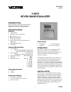
VSP-V-9975
Issue 4
1 947006
V-9975
SEVEN BAND EQUALIZER
INTRODUCTION
These instructions contain the specifications and
information necessary to install, operate, and
maintain the V-9975, Seven Band Equalizer.
SPECIFICATIONS
Features
• 7 active filters
• Modified 1 octave equalization
• + 12 dB boost or cut
• Constant Q equalization
• Power "ON" indicator
• Bypass switch to remove EQ from circuit
(slide type)
• High impedance output
• Line output
Nominal Specifications
• Type of Inputs:
Hi impedance 10K Ohms (unbalanced)
Stereo HiZ 10K Ohms (unbalanced)
• Type of Outputs: Line (balanced)
Hi impedance 10K Ohms (unbalanced)
• Frequency Response: 35Hz-20kHz +1dB
• Distortion: < 0.3%
• Frequency Centers: Band 1 = 60 Hz
2 = 200 Hz
3 = 560 Hz
4 = 1100 Hz
5 = 2200 Hz
6 = 4500 Hz
7 =10000Hz
Power Requirements
• -24VDC
• 150 mA
Dimensions/Weight
• 5.7" H x 8.1" W x 2.5" D
(14.5cm W x 20.6cm H x 6.4cm D)
• 2.8 lbs. (1.27 kg)
Environment
• Temperature: 0 to 50 Degrees C
• Humidity: 0-85% non-precipitating
OPERATION
The V-9975 is used to boost or attenuate specific
frequencies to improve voice intelligibility or
attenuate frequencies to help reduce feedback. The
unit can also be used to modify the frequency
response of speakers.
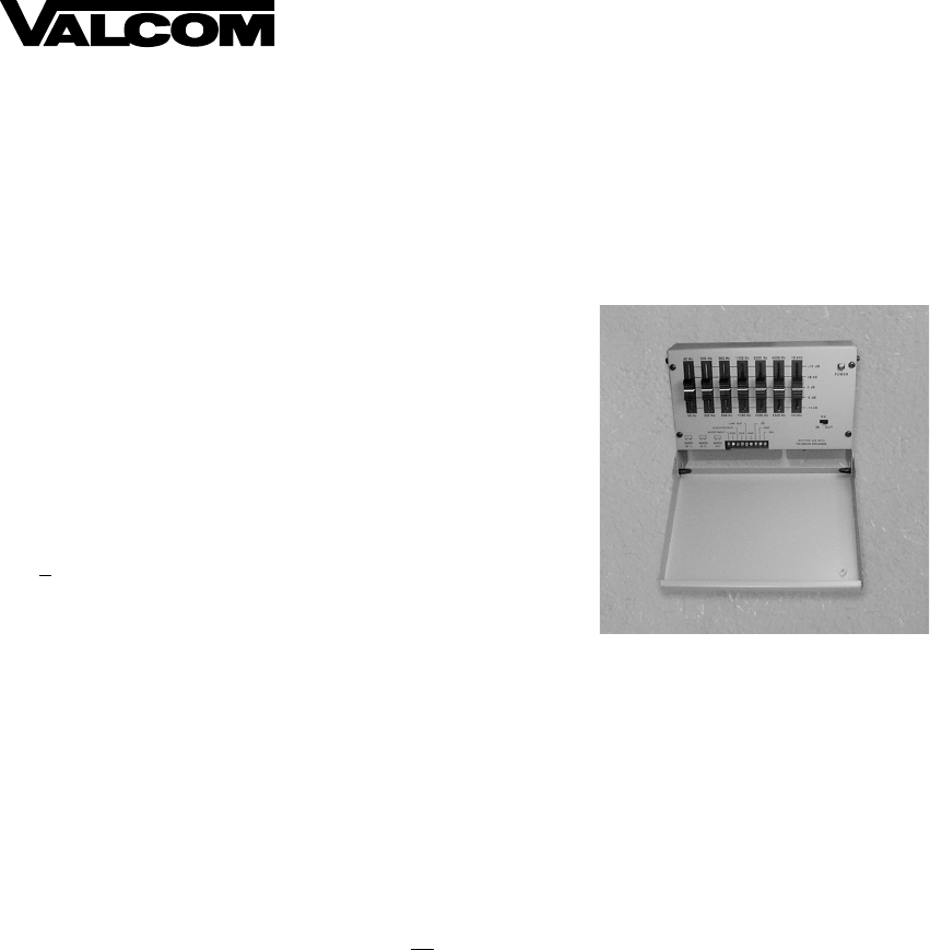
A "POWER" indicating LED, 7 slide controls (1 for
each of the bands), and an "EQ" bypass switch are
located on the front of the unit. The frequencies
boost/cut (1 to 12 dB), are modified with each filter's
slide control. The manual "EQ" bypass switch allows
comparison of before equalization, and after effect, in
the area being equalized. All frequency adjustments
are bypassed when the "EQ IN/OUT" switch is in the
"OUT" position.
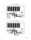
INSTALLATION
Connections are accomplished utilizing (3) phono
jacks (2 input, 1 output) and/or (9) screw terminals.
Only qualified service personnel should install the
V-9975. See Figures 1 and 2 for actual connections.
After all connections are made and slide controls
adjusted to the desired positions, close security cover
and tighten locking screws. All connections should
be made and double checked before DC power is
supplied to the unit.