


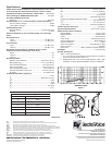
DL18MT
Low-Frequency
Reproducer
General Product Description
The DL18MT low-frequency reproducer is a 460 mm (18-inch), 8-ohm
driver designed for professional high-level, high-fidelity monitoring and
sound reinforcement. At the heart of this speaker is a carefully
engineered drive system. Its design assures linear, low distortion output,
high power capability and efficient heat transfer.
Incorporated into the design are three exclusive Electro-Voice
®
innovations. PROTEF™ coating (U.S. patent #4,547,632), a Teflon
®
-based coating, is applied to the inside diameter of the top plate.
Occasional violent power peaks of several seconds may expand a
transducer’s voice coil into contact with the top plate, causing failure.
PROTEF™ proides protection against such failure. The coating
lubricates any rubbing contact and provides electrical insulation between
the coil and the steel top plate. The Thermo Inductive Ring (TIR™) and
Flux Demodulation Device (FDD™), also included in the DL18MT
design, are aluminum castings fastened to the pole of the magnet. They
provided a shorted turn to control inductance and provide a major heat
transfer path from the voice coil, which improves power handling and
reduces thermal, dynamic-range compression.
The voice coil itself is constructed of edge-wound rectangular copper
wire, mounted on a rugged laminated polyimide former. The complete
assembly is fabricated using the most advanced epoxies, insulations
and materials available.
Great care was taken in the selection of diaphragm materials and
construction to ensure smooth, musical upper-bass reproduction and
accurate low-frequency shock capability (punch). The cone has a
moisture-repellent treatment, allowing it to be used in harsh and humid
conditions. (Do not expose the cone to direct water or sunlight.)
The DL18MT is a true high-fidelity woofer in every sense, being capable
of high output, low distortion and solid bass response.
Architects’ and Engineers’ Specifications
The low-frequency woofer shall have a nominal diameter of 457 mm
(18.0 in.), an overall depth of 188 mm (7.42 in.) and weigh less than 9.3
kg (20.5 lb). The frame shall be constructed of strong,
deformation-resistant die-cast aluminum. The magnet assembly shall
incorporate PROTEF™ protection, a TIR™ (Thermo Inductive Ring)
and FDD™ (Flux Demodulation Device) to reduce inductive coupling
and increase power handling. The cone and dust dome should withstand
use in damp and humid conditions. The voice coil shall have a diameter
of 64 mm (2.5 in.), a winding depth of 20.3 mm (0.8 in.) and be made of
edge-wound copper ribbon. The voice-coil former shall be made of
aerospace-grade polyimide laminate and bonded with high-temperature
epoxy adhesives. The performance specification of a representative
production unit shall be as follows: measured sensitivity (SPL at 1 m
(3.3 ft) with 1 watt input, 100- to 800-Hz pink noise) shall be in excess
of 95 dB. The halfspace reference efficiency shall be at least 2.9%. The
usable response shall be 30 to 3,000 Hz, and the nominal impedance
shall be 8 ohms. The EIA rated power shall be 400 watts. The
low-frequency transducer shall be the Electro-Voice DL18MT.
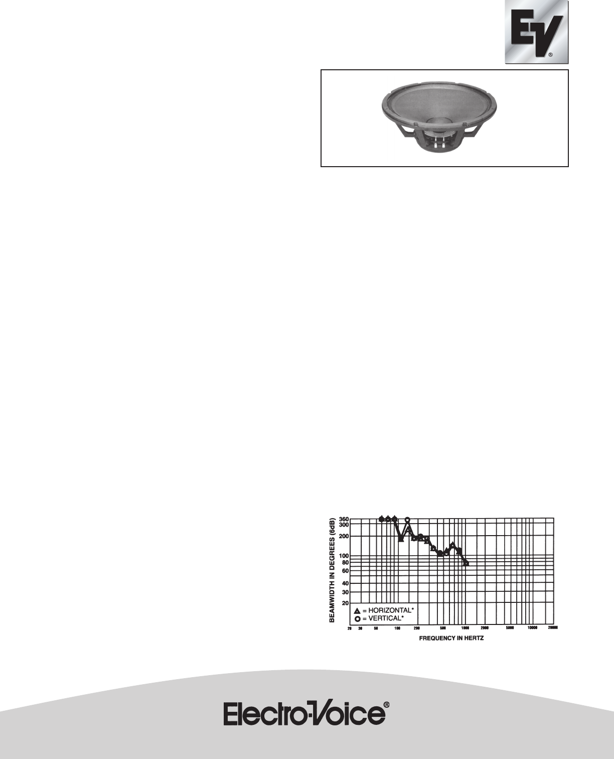
Directional Characteristics
The directional characteristics of the DL18MT in the 7.4-cubic-foot
TL18-1 vented enclosure were measured in ElectroVoice’s large
anechoic chamber. The test signal was one-third-octave filtered pink
noise centered at the frequencies indicated. All directional information
was measured at 20 feet. Figure 1 shows the horizontal and vertical
beamwidths. Beamwidth is the angle at which the horizontal and vertical
polar responses have decreased in level by 6 dB when compared to
the axial frequency response. Figure 2 illustrates the total directivity of
the DL18MT. The directivity factor R
q
(Q) is the relative value, at a point,
of the DL18MT when compared to an ideal spherical response. The
directivity index, D
i
, is calculated by the formula: D
i
= 10 log
10
R
q
.
Electrical Connections
The DL18MT is fitted with a pair of plated, frame-mounted connectors
with color-coded ends. Electrical connection is made by pushing down,
inserting wire completely through the rectangular slot and releasing
pressure. One conductor of #9 stranded, #8 AWG solid, a pair of twisted
#15 AWG stranded or a pair of #14 AWG solid conductors will fit.
Typical Amplifier Size
400-800 watts per woofer is the optimal amplifier size. Amplifiers of this
size will allow maximum output with minimal risk of speaker damage
when properly used. Smaller amplifiers can also be used with excellent
results.
Typical Enclosures
The most extended bass, lowest distortion and best control is usually
realized in properly designed vented enclosures. In such designs, the
vent, or port, actually provides the lowest octave of output. The vent is
driven to full acoustic output by a relatively small motion of the speaker
cone itself, acting through the air contained within the enclosure. The
excursion of the DL18MT at these frequencies is much reduced
compared to sealed or open-back enclosures, directly reducing harmonic
distortion and the possibility of speaker bottoming. Thiele-Small
parameters are provided so designers can tailor the response to suit
their needs.
Normally Tuned Enclosures
A 1.8 cubic-foot enclosure tuned to 55 Hz has a smooth extended
response to below 50 Hz. The 1.1 cubic-foot enclosure “bumps up”
above 70 Hz but has less extended low-bass output.
Figure 1