


Before Installation
•Mount the unit either inside the trunk or under a seat.
•Choose the mounting location carefully so the unit will not interfere with the normal movements of the
driver and it will not be exposed to direct sunlight or hot air from the heater.
•Do not install the unit under the floor carpet, where
the heat dissipation from the unit will be
considerably impaired.
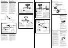
First, place the unit where you plan to install it, and
mark the positions of the four screw holes on the
surface of the mounting board (not supplied). Then
drill the holes approximately 3 millimeters (mm) in
diameter and mount the unit onto the board with the
supplied mounting screws. The supplied mounting
screws are 15 mm long. Therefore, make sure that
the mounting board is thicker than 15 mm.
10
10
0
40 100 1k
Sony Corporation 2001 Printed in Korea
XM-3001SXD
Owner’s Record
The model and serial numbers are located on the bottom of the unit.
Record the serial number in the space provided below.
Refer to these numbers whenever you call upon your Sony dealer regarding this product.
Model No. XM-3001SXD Serial No.
MONAURAL
Power Amplifier
Operating Instructions
Mode d’emploi
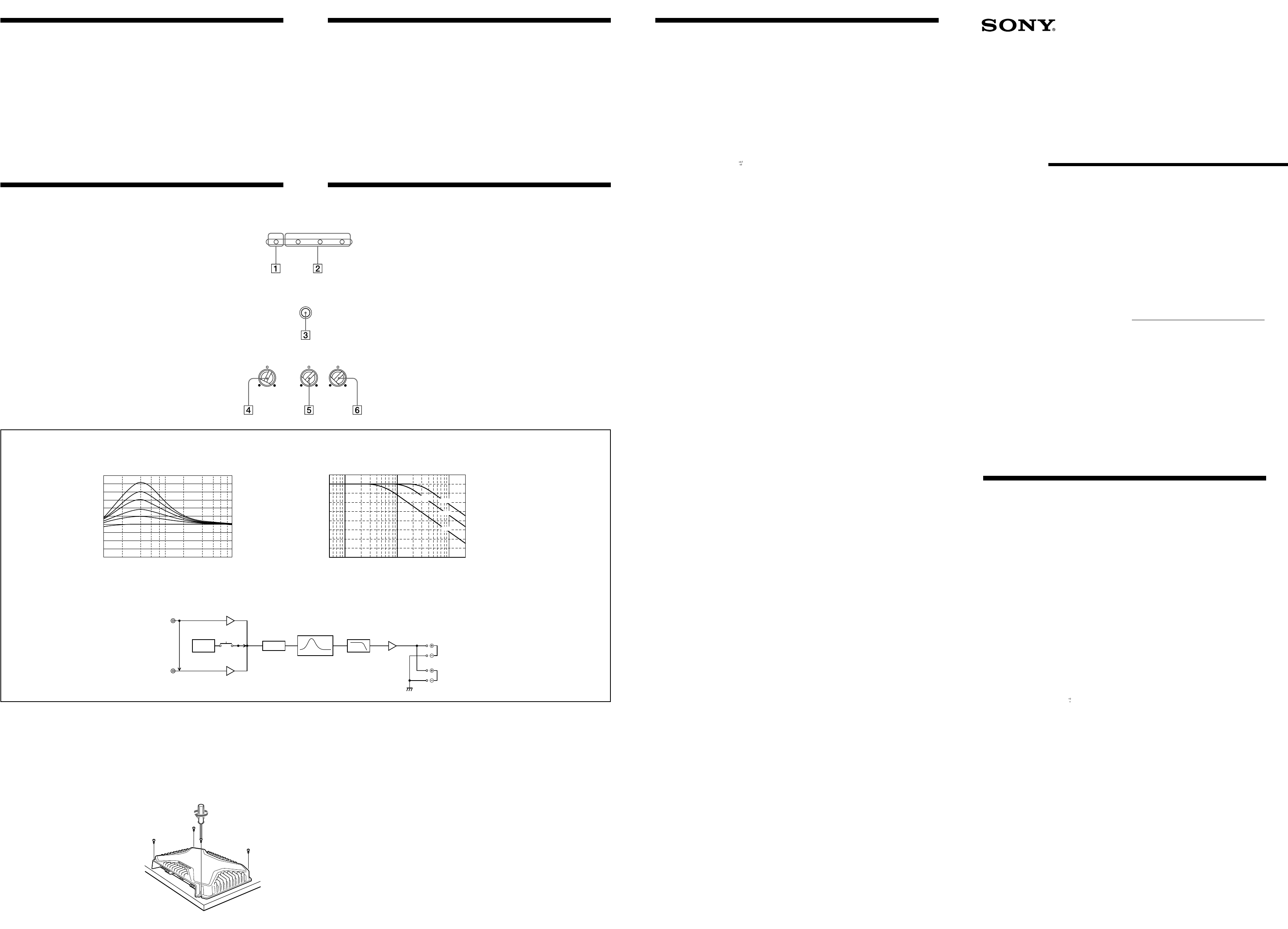
Location and Function of Controls
1 POWER indicator
Lights up in green during operation.
2 PROTECTOR indicator
•OVER CURRENT:
Lights up in red when receiving a powerful signal.
•OFFSET:
Lights up in red when the voltage going out to the Speaker terminal or the
Pin Jack is too high.
•THERMAL:
Lights up in red when the temperature rises to an unsafe level.
3 TEST-TONE button
When the button is pressed, operations of a built-in Oscillator allow the
System conditions to check.
Hearing the tones, the System is in good conditions.
4 Cut-off frequency adjustment control
Sets the cut-off frequency (50–300 Hz) for the low-pass filters.
5 LOW BOOST level control
Turn this control to boost the frequencies around 40 Hz to a maximum of 10
dB.
6 LEVEL adjustment control
The input level can be adjusted with this control when using source
equipment made by other manufacturers. Turn it to MAX when the output
level of the car audio seems low.
Emplacement et fonction des commandes
1 Indicateur POWER
S’allume en vert en cours fonctionnement.
2 Indicateur PROTECTOR
• OVER CURRENT:
S’allume en vert lors de la réception d’un signal puissant.
• OFFSET:
S’allume en rouge lorsque la tension de sortie vers le terminal du haut-
parleur ou la prise à broches est trop élevée.
• THERMAL:
S’allume en rouge lorsque la température atteint un niveau trop dangereux.
3 Touche TEST-TONE
Lorsque vous appuyez sur cette touche, la mise en marche d’un oscillateur
intégré permet de vérifier le système.
Si vous entendez le signal, le système est en bonne condition.
4 Commandes de réglage de la fréquence de coupure
Règle la fréquence de coupure (50–300 Hz) pour les filtres passe-bas.
5 Commande de niveau LOW BOOST
Tournez cette commande pour amplifier les fréquences autour de 40 Hz
jusqu’à un maximum de 10 dB.
6 Commande de réglage LEVEL
Le niveau d’entrée peut se régler avec cette commande lors de l’utilisation
d’équipements source d’autres fabricants. Mettez-le sur MAX lorsque le
niveau de sortie de l’installation audio paraît faible.
* Class D Technology
The Class D Technology is a method to convert and
amplify music signals with MOSFETs to high speed pulse
signals.
The unit can drive enough a speaker with Low Impedance
(1 Ω).
Furthermore, it features high efficiency and low heat
generation.
Features
•Maximum power output of 600 watts (at 4 Ω).
•Class D Technology*
•This Power Amplifier is produced only for
Subwoofer.
•Direct connection can be made with the speaker
output of your car audio if it is not equipped
with the line output (High level input
connection).
•Built in variable LPF (Low-pass filter), and low
boost circuit.
•Protection circuit and indicator provided.
•TEST-TONE functions of easy-checking for the
System performance.
•Two speakers terminals for parallel connections
added.
Spécifications
Circuiterie Circuit OTL (sortie sans
transformateur)
Alimentation par impulsions
Entrées Prises à broche RCA
Connecteur d’entrée haut niveau
Sorties Bornes de haut-parleurs
Prises à broches à sortie directe
Impédance des haut-parleurs
1 – 8 Ω
Sorties maximales 600 W (à 4 Ω)
1200 W (à 2 Ω)
Sorties nominales (tension d’alimentation à 14,4 V)
300 W (20 Hz – 300 Hz, 0,2 % THD,
à 4 Ω)
600 W (20 Hz – 300 Hz, 0,6 % THD,
à 2 Ω)
1000 W (20 Hz – 300 Hz, 1,2 %
THD, à 1 Ω)
Réponse en fréquence
5 Hz – 300 Hz (
dB)
Distorsion harmonique
0,06 % ou inférieure (à 100 Hz, 4 Ω)
Plage de réglage du niveau d’entrée
0,2 – 6,0 V (prises à broche RCA)
0,4 – 12,0 V (entrée haut niveau)
Filtre passe-bas 50 – 300 Hz, –12 dB/oct
Amplification de basses fréquences
0 – 10 dB (40 Hz)
Tension d’alimentation
10,5 – 16 V
Courant à la sortie nominale: 40 A (à 4 Ω)
Entrée de télécommande: 2 mA
Dimensions Approx. 358 × 50 × 264 mm
(14
1
/8 × 2 × 10
1
/2 po.) (l/h/p) à
l’exclusion des parties et
commandes saillantes
Poids Approx. 3,5 kg (7 liv. 11 oz.) sans les
accessoires
Accessoires fournis
Vis de montage (4)
La conception et les spécifications sont sujettes à
modifications sans préavis.
Caractéristiques
•Puissance de sortie maximale de 600 watts
(à 4 Ω).
•Technologie de classe D*
•Cet amplificateur de puissance est conçu
uniquement pour un haut-parleur d’extrêmes
graves.
•Une connexion directe est possible avec la sortie
haut-parleur de votre autoradio si celle-ci n’est
pas équipée d’une sortie de ligne (connexion
d’entrée haut niveau).
•Filtre passe-bas (LPF), variables et circuit
d’amplification des graves intégrés.
•Avec circuit et indicateur de protection.
•TEST-TONE functions of easy-checking for the
System performance.
•Deux bornes de haut-parleurs ajoutées pour des
raccordements en parallèle.
* Technologie de classe D
La technologie de classe D est une méthode permettant de
convertir et d'amplifier des signaux musicaux grâce à des
MOSFET pour obtenir des signaux par impulsion à
grande vitesse.
L'appareil peut piloter un haut-parleur à faible impédance
faible (1 Ω).
De plus, il appartient à la génération d'appareils alliant
efficacité de haut niveau et un faible dégagement de
chaleur.
Circuit Diagram / Schéma du circuit
LOW BOOST
FREQUENCY Hz
dB
FREQUENCY Hz
dB
Cut-off frequency/Fréquence de coupure
POWER/PROTECTOR
OVER CURRENTPOWER OFFSET THERMAL
TEST
TONE
FILTER
LEVEL
LOW BOOST
(40Hz)
MIN MAX0dB +10dB
50Hz 300Hz
LEVEL
Buffer
AMP
Power
LPF
Lch
Rch
LOW BOOST
TEST
TONE
10
0
-10
-20
-30
-40
-50
-60
-70
-80
10 100 1k
50Hz
LOW PASS
150Hz
300Hz
Specifications
AUDIO POWER SPECIFICATIONS
POWER OUTPUT AND TOTAL HARMONIC DISTORTION
300 watts minimum continuous average power into 4 ohms, 20 Hz to
300 Hz with no more than 0.2% total harmonic distortion per Car
Audio Ad Hoc Committee standards.
Other Specifications
Input level adjustment range
0.2 – 6.0 V (RCA pin jacks)
0.4 – 12.0 V (High level input)
Low-pass filter 50 – 300 Hz, –12 dB/oct
Low boost 0 – 10 dB (40 Hz)
Power supply voltage
10.5 – 16 V
Current drain at rated output: 40 A (at 4 Ω)
Remote input: 2 mA
Dimensions Approx. 358 × 50 × 264 mm
(14
1
/8 × 2 × 10
1
/2 in.) (w/h/d) not
incl. projecting parts and controls
Mass Approx. 3.5 kg (7 lb. 11 oz.) not
incl. accessories
Supplied accessories
Mounting screws (4)
Design and specifications are subject to change
without notice.
3-231-699-11 (2)
Circuit system OTL (output transformerless)
circuit
Pulse power supply
Inputs RCA pin jacks
High level input connector
Outputs Speaker terminals
Through out pin jacks
Speaker impedance
1 – 8 Ω
Maximum outputs 600 W (at 4 Ω)
1200 W (at 2 Ω)
Rated outputs (supply voltage at 14.4 V)
300 W (20 Hz – 300 Hz, 0.2 %
THD, at 4 Ω)
600 W (20 Hz – 300 Hz, 0.6 %
THD, at 2 Ω)
1000 W (20 Hz – 300 Hz, 1.2 %
THD, at 1 Ω)
Frequency response
5 Hz – 300 Hz (