


Operating Instructions
Cordless Stereo
Headphone System
WARNING
To prevent fire or shock hazard, do
not expose the unit to rain or
moisture.
To avoid electrical shock, do not
open the cabinet. Refer servicing
to qualified personnel only.
WARNING
You are cautioned that any changes or
modifications not expressly approved in this
manual could void your authority to operate this
equipment.
Owner’s Record
The model number is located on the top of the
transmitter and the inner side of the headband.
The serial number is located at the bottom of the
transmitter and inside the battery compartment of
the headband.
Record these numbers in the spaces provided
below. Refer to them whenever you call upon your
Sony dealer regarding this product.
Model No. MDR-IF125RK
Transmitter TMR-IF125R
Headphones MDR-IF120
Serial No.
Transmitter
Headphones
Welcome!
Thank you for purchasing the Sony MDR-IF125RK
Cordless Stereo Headphone System. Before
operating the unit, please read this manual
thoroughly and retain it for future reference.
Some features are:
• Cordless system that allows you to listen to a
program free from the restriction of a cord.
• Broad horizontal listening area that gives you
superb sound virtually anywhere in the room.
• Self-adjusting headband for fitting your head
perfectly.
• The VOL control adjusts the volume level of both
channels.
• The supplied rechargeable battery can be used to
power the headphones.
3-858-456-12(1)
Sony Corporation © 1996 Printed in Korea
MDR-IF125RK
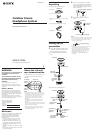
Unpacking
Check that you have the following items:
• Transmitter
• AC power adaptor
• Connecting cord (phono plugs ˜ stereo mini
plug)
• Ni-Cd Rechargeable battery NC-AA (HJ)
• Headphones
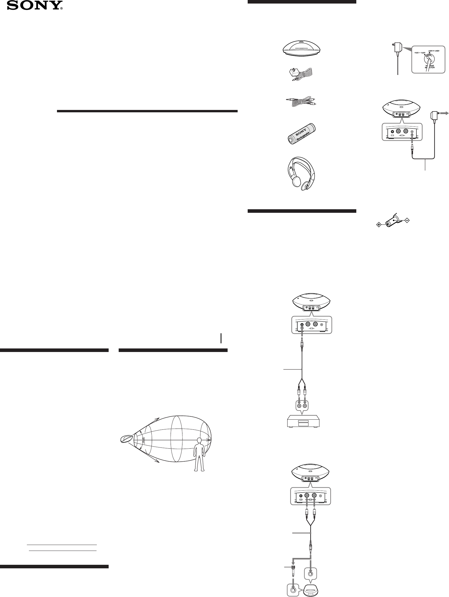
Setting up the
transmitter
1 Connect the transmitter to audio/video
equipment. Select one of the hookups
below depending on the jack type:
a To connect to LINE OUT or REC OUT
jacks
b To connect to a headphones jack
B
R
AUDIO IN DC IN 9V
L
¥
A
Transmitter
Right
channel
(red)
Left
channel
(white)
Stereo system,
TV, VCR, etc.
Connecting
cord (supplied)
to LINE OUT
or REC OUT
jacks
to AUDIO IN B jack
B
R
AUDIO IN DC IN 9V
L
¥
A
Transmitter
to a headphones
jack (stereo
mini jack)
Connecting cord
(supplied)
to AUDIO IN A jacks
Right channel
(red)
Discman,
WALKMAN
*
, TV,
VCR, etc.
to a headphones
jack (stereo
phone jack)
Unimatch plug
adaptor (not
supplied)
Left channel
(white)
2 If your AC power adaptor is equipped
with a voltage selector, before connecting
the AC power adaptor to an AC outlet,
set it to the operating voltage in your area
with a screw driver.
3 Connect the transmitter to a power
source.
Notes
•Do not connect to the AUDIO IN A jacks and B jack at the
same time. If you do so, the audio signals may be mixed.
•Use only the supplied AC power adaptor. Do not use
any other AC power adaptor.
•If the plug of the AC power adaptor does not fit in the
AC outlet, use the supplied AC plug adaptor.
•When you connect the connecting cord directly to an
earphone jack, the audio signal will not be output
through the right channel. In such a case, use the
separately sold PC-236HG plug adaptor.
* WALKMAN is a registered trademark of Sony
Corporation.
B
R
AUDIO IN DC IN 9V
L
¥
A
Transmitter
to an AC
outlet
to DC IN 9V jack
AC power adaptor (supplied)
Polarity of the plug
AC power adaptor (supplied)
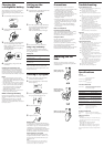
About the infrared
rays communication
The illustration below shows the approximate area
covered by the infrared rays emitted from the
transmitter.
Notes
• This system utilizes infrared rays for communication so
noise (hissing) can be heard in the headphones as you
move farther away from the transmitter. The sound will
also cutoff and noise occur if the infrared rays are
blocked. These are characteristics of infrared ray
communication and do not indicate an equipment
breakdown.
• The infrared rays will not penetrate walls or opaque
glass, therefore, be sure to stay within sight of the
transmitter.
• When you use the headphones inside the area illustrated
in the diagram, the transmitter can be placed in the front,
behind or by the side of the listener.
• The sound you hear varies according to your position
and the transmitter position. Try finding a position
which yields the best sound.
45°
45°
Approx. 7 m (23 ft.)
Transmitter
Approx. 3 m
(118
1
/
8
in.)
Approx. 3 m
(118
1
/
8
in.)
Infrared ray
TMR-IF125R
MDR-IF120