


1. INTRODUCTION
Model 318K
In this package, you will find a keyless entry transmitter with 3V
lithium batteries and a clip.
It is recommended to randomly set the operation code for your
transmitter and receiver to avoid interference from other devices.
Fo llow the instructions below to change the operation code.
This instruction does not demonstrate how the receiver should be
installed, please refer to the user’s instructions of the receiver.
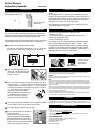
Pry off the cover on the back of the transmitter.
You will see 10 connectors labeled from “1” to “10”, as shown.
(the connectors setting may not be the same as shown)
1
Keyless Entry Transmitter
(Batteries inside)
Skylink
®
Wireless
Keyless Entry Transmitter
2 You can randomly remove some
connectors, leaving some in place.
A connector can be removed with
the clip, as shown.
Clip
If the connector is placed on the top and middle posts, that
column is set on “ + ” . If the connector is placed on the middle
and bottom posts, that column is set on “ - ”. If the connector
is removed completely, (not placed on any posts), it is set to
“ 0 ”. (see diagram for examples of
how to set a column to the three
different positions). When removing
a connector to set a column to “ 0 ”,
save the connector in case you
change the code at a later date.
After setting up the code connectors on the keypad transmitter,
you are ready to set the same code on the receiver.
3
4
‘+’
‘-’
‘0’
2. CHANGE THE OPERATION CODE FOR TRANSMITTER
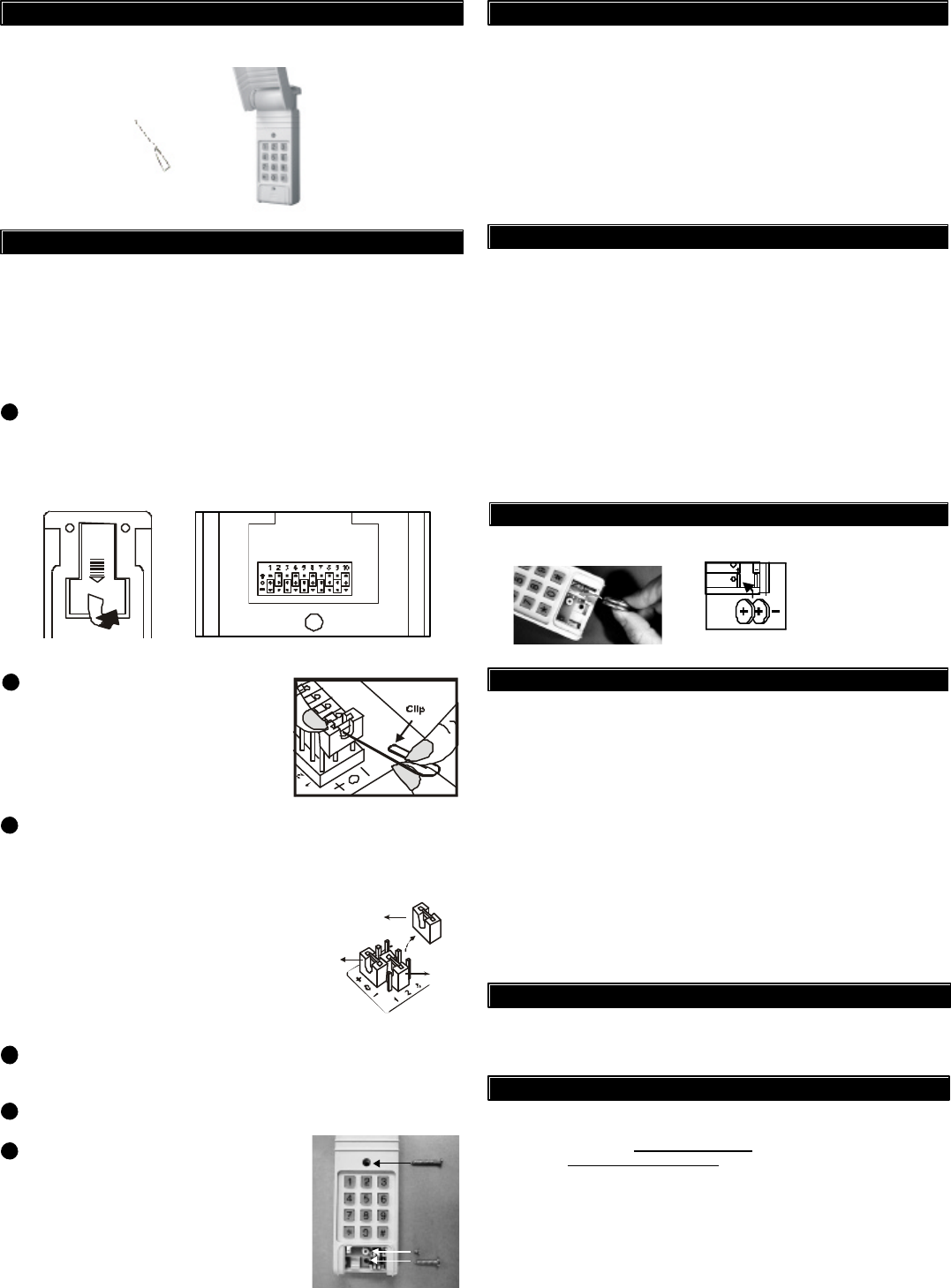
You can now mount the transmitter on
a desired location.
Lift up the cover and insert screw
above the keypad in the slot provided (a).
Remove the battery cover and insert
the second screw in the lower slot (b).
Tighten all screws. Replace the battery
cover, insert and tighten screw (c).
(a)
(c)
(b)
6
Enter [0,0,0,0] [#] will open the garage door.5
If, within one year from date of purchase, this product should become defective
(except battery), due to faulty workmanship or materials, it will be repaired or
replaced, without charge. Proof of purchase and a Return Authorization are required.
7. WARRANTY
3. KEYPAD OPERATION
6. FCC
NOTE:
The backlight comes on and a beep is emitted when any key is
pressed. The backlight of the keypad may not be visible when it
is too bright outside. When any key is pressed, the next key must
be pressed w ithin 5 seconds or the backlight turns off and the
sequence is cancelled. You must begin again.
If the keypad does not emit a beep when pressed, wait a few
seconds and press the key again.
4. CHANGE PIN
Follow the instructions below to change the PIN.
To change your PIN:
1. Enter the current PIN, (factory default PIN 0 0 0 0), press ,
2. Enter new 4 digit PIN, press ,
3. Enter new PIN again, press .
For example, if you are changing the PIN number from 0000 to
1234, enter the following sequence, 0000, ,1234, ,1234, .
If confirmed, the backlit LED flashes and the unit emits a long beep.
*
*
**
If you do n ot hear 3 beeps after the 4-digit PIN and [#] is entered,
that means you have entered an incorrect PIN, and the keypad
transmitter will not operate your garage door.
*
*
Two 3 volt Lithium type (CR2032) batteries (included).
It is time to change
the batteries when
the backlight no
longer appears.
+
-
Battery Compartment
5. BATTERY
8. CUSTOMER SERVICE
CUSTOMER SERVICE
17 Sheard Avenue, Brampton, Ontario, Canada L6Y 1J3
Email:support@skylinkhome.com
http://www.skylinkhome.com
P/N. 101A261-001 Rev.1
©2005 SKYLINK GROUP
If you would like to order Skylink’s products or have difficulty getting them to work,
please :
1. visit our FAQ website at www.skylinkhome.com , or
2. email us at support@skylinkhome.com, or
3. call our toll free at 1-800-304-1187 from Monday to Friday, 9 am to 5 pm EST.
Fax (800) 286-1320
This device complies with Part 15 of the FCC Rules. Operation is subject to the following two conditions:
(1) This device may not cause harmful interference, and (2) This device must accept any interference
received, including interference that may cause undesired operation.
WARNING:
Changes or modifications to this unit not expressly approved by the party responsible for compliance could
void the user’s authority to operate the equipment.
NOTE:
This equipment has been tested and found to comply with the limits for a Class B digital device, pursuant
to Part 15 of the FCC Rules. These limits are designed to provide reasonable protection against harmful
interference in a residential installation. This equipment generates, uses and can radiate radio frequency
energy and, if not installed and used in accordance with the instructions, may cause harmful interference
to radio communications.
However, there is no guarantee that interference will not occur in a particular installation. If this equipment does
cause harmful interference to radio or television reception, which can be determined by turning the equipment
off and on, the user is encouraged to try to correct the interference by one or more of the following measures:
- Reorient or relocate the receiving antenna.
- Increase the separation between the equipment and receiver.
- Connect the equipment into an outlet on a circuit different from that to which the receiver is connected.
- Consult the dealer or an experienced radio/TV technician for help.