


Model 527C User Guide
©2005 Shure Incorporated
27C2084 (Rev. 5)
Printed in U.S.A.
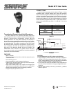
Transistorized Dynamic Hand-Held Microphone
The Shure Model 527C is a dynamic hand-held communica-
tions microphone for use in a variety of mobile and fixed-station ap-
plications, including police, transportation, amateur radio and
similar applications. The 527C offers extremely low sensitivity to
hum pickup and low susceptibility to radio-frequency interference.
A built-in solid state amplifier permits the use of up to 30 m (100 ft)
of unshielded cable. The modular construction of the 527C allows
the cartridge, switch, and cable to be replaced in a matter of min-
utes, if necessary. The 527C fits naturally and comfortably in the
hand and is not adversely affected by heat or humidity. The
ARMO-DUR
®
case is immune to oil, grease, fumes, salt spray,
sun, rust and corrosion, and is outstanding in its ability to withstand
mechanical shocks and vibration.
FEATURES
• Built-in amplifier
• Frequency response from 300 to 5,000 Hz, tailored for voice
communications
• Low sensitivity to hum
• Low susceptibility to radio-frequency interference
• “Million-Cycle” leaf-type switch stands up under severe oper-
ating conditions and constant use
• High-impact ARMO-DUR
®
case—lighter and stronger than
die-cast metal, comfortable to the touch in hot or cold weather
• Rugged and dependable under all operating conditions
• Long-life neoprene-jacketed coil cord
CONNECTIONS
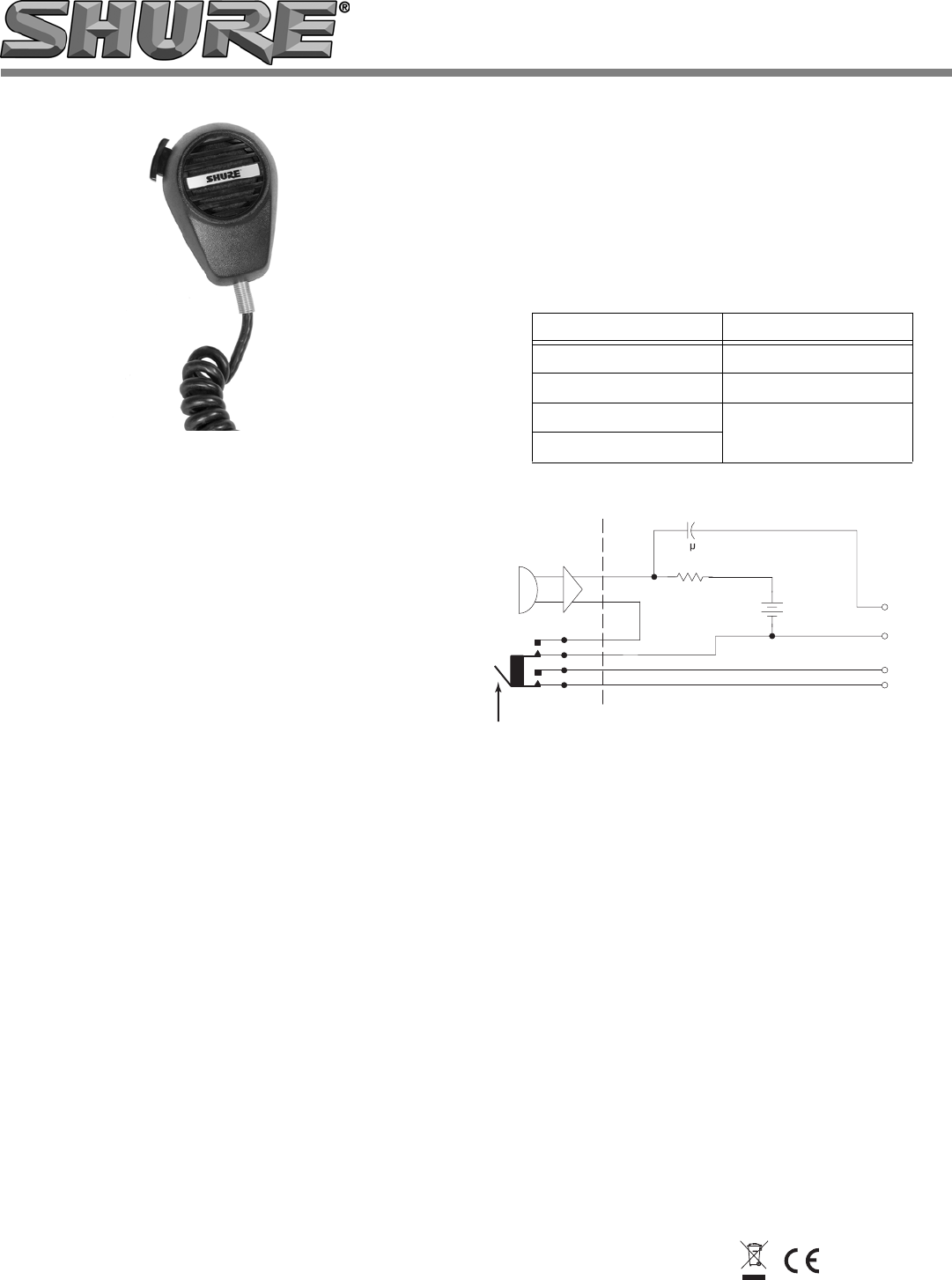
A typical external operating circuit is shown in Figure 1. Circuit
parameters such as supply voltage, load, current and sensitivity
may be selected using the curves shown in Figures 3 and 4. If, for
instance, the available supply voltage is 16 Vdc and a current drain
of 4 mA is desired, a load resistance (RL) of 2.2KΩ is necessary.
With a supply voltage of 16 Vdc and a load resistance of 2.2KΩ, the
relative sensitivity is approximately +8 dB, or –3 dB output level ref-
erenced to the specified output level of –11 dB with 10 Vdc and a
470Ω load.
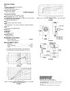
CABLE-TO-CONNECTOR WIRING
TABLE 1
TYPICAL OPERATING CIRCUIT
FIGURE 1
CAUTION:
To avoid damage to the 527C, observe the following:
•
Supply voltage (V) must be between 4 and 35 Vdc. Voltages ex-
ceeding 35 Vdc may substantially reduce the life of the micro-
phone. Voltages below 4 Vdc are not sufficient for microphone
amplifier operation (although no damage will occur).
•
Do not exceed the maximum allowable current (dissipation lim-
it) for the various combinations of supply voltages and load re-
sistances.
•
Maintain proper polarity for the red (+) and black (–) leads as
shown in Figure 1.
WIRE COLOR FUNCTION
BLACK AUDIO GROUND
RED AUDIO
GREEN
RELAY CIRCUIT
WHITE
AUDIO
OUTPUT
TRANSMIT
RELAY
CIRCUIT
LOAD RESISTANCE
R
L
5
F
RED (+)
AMPLIFIER
CARTRIDGE
MICROPHONE
BLACK (–)
GREEN
WHITE
SWITCH
+
SUPPLY
VOLTAGE
V
S
5