


Model 514B User Guide
©2014 Shure Incorporated
27C1387 (Rev. 7)
Printed in U.S.A.
GENERAL
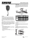
The Shure 514B is a low impedance, dynamic, hand-held
microphone designed for paging and public address systems. It
provides clear, natural voice response and high intelligibility.
The 514B connects to microphone inputs rated at 19 to 300 .
It can be used in applications that require long cable lengths, or
where severe hum conditions are present. For connection to high
impedance inputs, use Shure A95 Series Line Matching Trans-
formers.
The microphone is provided with a four-conductor (two
shielded) coiled cable and a “Million-Cycle” leaf-type switch
designed for constant use under the most rigorous conditions. The
514B fits naturally and comfortably in the hand and is not affected
by heat or humidity. The exclusive ARMO-DUR
case resists
mechanical shocks and vibration, and is impervious to oil, fumes,
salt spray, ultraviolet radiation, and corrosion.
Features
• Smooth, extended frequency response from 100 to 6,000 Hz-pro-
vides highly intelligible voice response
• “Million-Cycle” leaf-type switch-provides outstanding reliability,
even under extreme conditions
• Tough ARMO-DUR
case
• Long-life, neoprene-jacketed, coiled cable
• Supplied mounting bracket fits hang-up button on back of
microphone
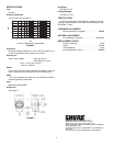
CONNECTIONS
Refer to Figure 1 and Table 1 below. The GREEN wire is con-
nected to the positive audio input, the WHITE wire is connected to
the negative audio input, and the SHIELD is connected to chassis
ground. The RED and BLACK leads control the external relay or
switching circuit.
INTERNAL CONNECTIONS
FIGURE 1
Table 1. Typical Cable-to-Connector Wiring
NOTE: The RED and BLACK leads are not part of the audio
circuit. These wires provide a contact closure when the
press-to-talk switch is depressed. This closure may be used to
control an external relay or a transmit/receive circuit.
OPERATION
To operate the microphone, simply hold down the press-to-talk
switch and begin speaking. Release the switch when you are fin-
ished speaking.
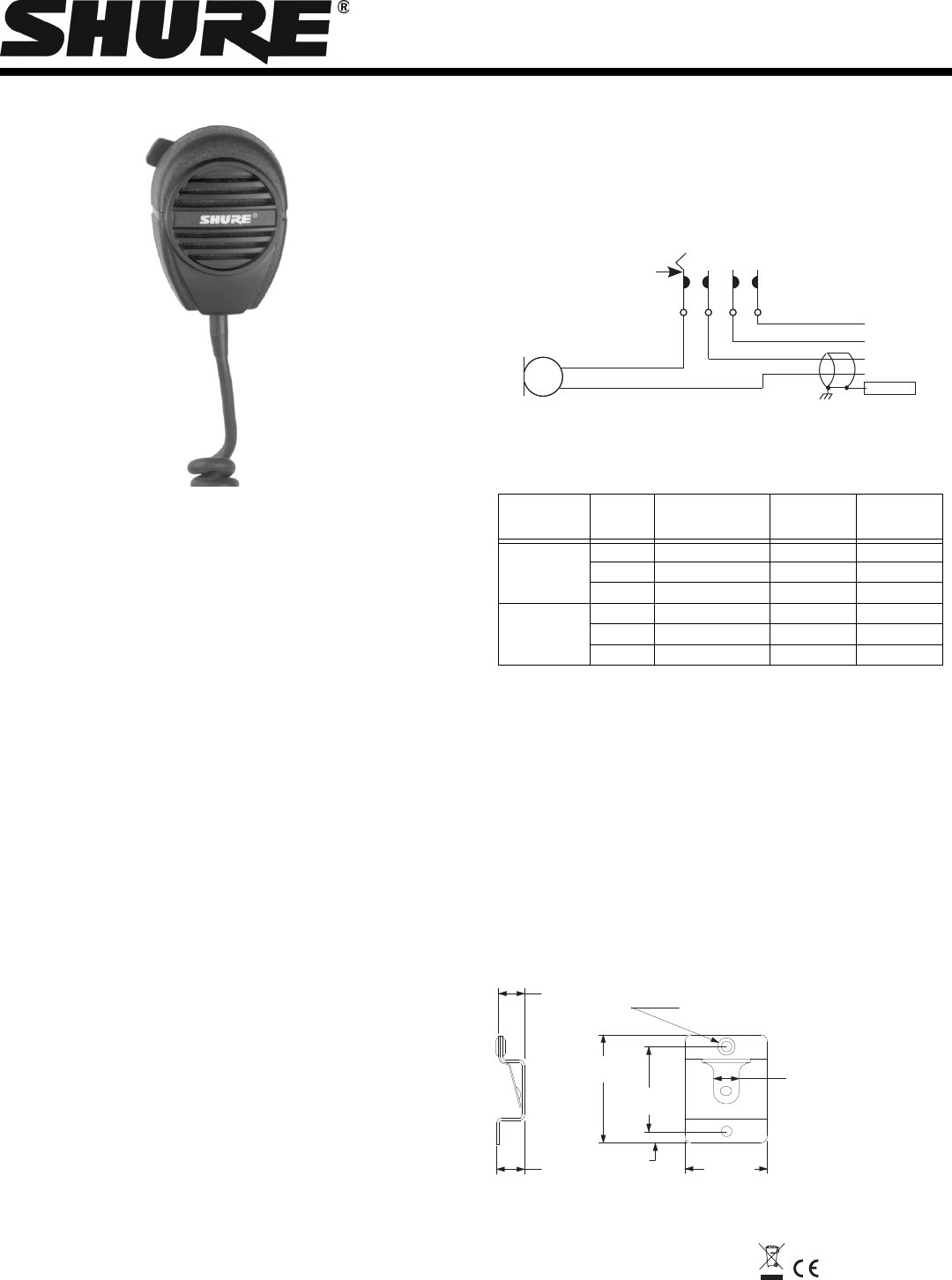
MOUNTING
The 514B is supplied with a mounting bracket to provide a
snap-in hang-up for the microphone when it is not in use. The
bracket has mounting holes with clearance for No. 8 screws. See
Figure 2 below.
MOUNTING BRACKET
Figure 2
INPUT TYPE
WIRE
COLOR
FUNCTION XLR
CONNECTOR
1/4 IN. PHONE
JACK
BALANCED GREEN AUDIO + PIN 2 TIP
WHITE AUDIO - PIN 3 RING
SHIELD CHASSIS GROUND PIN 1 SLEEVE
UNBALANCED GREEN AUDIO - TIP
WHITE AUDIO - SLEEVE
SHIELD CHASSIS GROUND - SLEEVE
BLACK
BLACK
RED
RED
GREEN
GREEN
WHITE
WHITE
YELLOW
YELLOW
CAR
CAR
TRIDGE
TRIDGE
PRESS
PRESS–T
O-T
O-T
ALK
ALK
SWITCH
SWITCH
CABLE
CABLE
SHIELD
SHIELD
+
46 mm
36.5 mm
4.7 mm
34.5 mm
10.3 mm
9.5 mm
9.1 mm
(23/64 IN.)
(3/8 IN.)
(1-13/16 IN.)
(1-7/16 IN.)
(3/16 IN.)
(1-23/64 IN.)
(13/32 IN.)
MOUNTING HOLES,
CLEARANCE FOR
No. 8 SCREWS