


RF-RBKIT Wireless HD Audio Starter Kit
QUICK SETUP GUIDE
SPEAKER-OUT (4-8 Ohm)
R
L
120V~,60Hz
AC IN
11
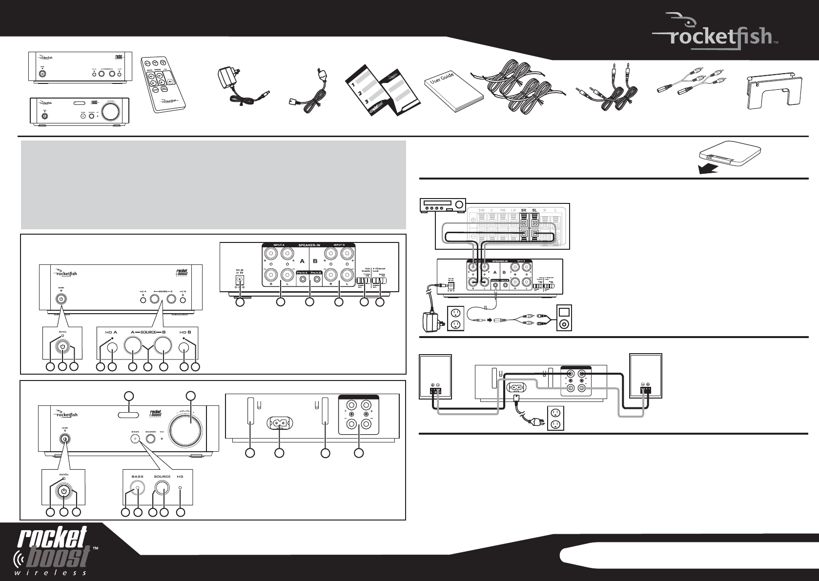
1 Standby LED
2 Power/Join button
3 Power/Join indicator
4 BASS button
5 Bass indicator
6 SOURCE indicator
7 SOURCE button
8 HD indicator
1 Standby LED
2 Power/Join button
3 Power/Join indicator
4 HD A indicator
5 HD A button
6 Source A button
7 Source A/B LED indicator
8 Source B button
IR remote
DC adapter
(for sender)
AC power cable
(for receiver)
Speaker cable,
3 ft (x4)
Cable spool
(for receiver)
User Guide
Step 4 Establishing communication
The sender and receiver packaged together were pre-joined at the factory, so if you are only using one
sender and receiver set, no further conguration is needed. If an active link is established between them,
the Power/Join indicators on both units will light steadily (no blink). If your sender and receiver are
not correctly linked (the power LEDs will ash slowly) or you need to add additional Rocketboost products, see
your User Guide for more information. Make sure the Source A or B LED is illuminated on the sender for the
channel that you have connected to your network for the audio transmission to be active.
Press the SOURCE button on the receiver until the audio channel you desire is playing.
Adjust the volume as desired.
11
12
13
14
15
16
9 HD B button
10
HD B indicator
11 DC IN jack
12 SPEAKER IN A jacks
13 Pre-in A/B jack
14 SPEAKER IN B jacks
15 Hub Enable switch
16 4 -Channel Lock switch
12 13 14
9 IR sensor
10 VOLUME knob
11 Removable cable spool slot
12 AC IN jack
13
Removable cable spool slot (line level)
14 SPEAKER OUT jacks
SPEAKER-OUT (4-8 Ohm)
R
L
120V~,60Hz
AC IN
Step 3 Connecting the receiver
Step 2 Connecting the sender
Connecting to an amplier
(surround mode is described below, as an example)
Connect the right surround speaker terminals of your amplier
to the right speaker terminals of the sender by connecting the
red speaker wire to the red (+) terminals, and the black
speaker wire to the black (-) terminals. Repeat to connect the
left surround speaker terminals.
Connecting to an external audio source
(such as an MP3 player)
Connect external audio source(s) to the Pre-in A and/or B jacks
on the rear of sender using the 3.5 mm male-to-male stereo
cable and the 3.5 mm female-to -RCA stereo cable.
Note: The Input A/Input B buttons on the remote control allow
you to select between the Speaker in or Pre in (line level). Each
press of the button will toggle to the other source. The unit
must be powered up for these buttons to operate and the
state when powered down will be remembered.
Connect the right surround speaker
to the right speaker terminals on the
receiver. Use a red speaker wire to
connect the red (+) terminals and a
black speaker wire to connect the
black (-) terminals.
Repeat this step to connect the left
surround speaker.
09-0474
Quick Setup Guide
QUICK SETUP GUIDE
3.5 mm male-to-male
stereo cable, 3ft (x2)
3.5 mm female-to-RCA
stereo cable,
6 in. (x2)
1
5
4
10
8
7
2
3
9
6
Wireless sender
Wireless receiver
Receiver
Sender
9
10
1
2
3
5
4
8
7
6
Package contents:
TM
TM
TM
TM
Step 1 Preparing the remote control
To activate the battery: Remove the tab from the bottom of the
remote control to enable the battery.
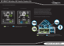
Please Read First
Every Rocketboost network must contain at least one hub device, which directs network data trac
and helps devices join the network. The network can have only one hub, which can be enabled by
using the hub switch on the back of all Rocketboost transmitters. The sender in this kit is set at the
factory for hub mode and the receiver has been pre-joined to this sender at the factory for easy
setup. If you have an existing Rocketboost network, the sender's hub mode switch should
be set to Disable. The sender and receiver also need to be joined to your existing hub device
(the one with the green power LED).
See your User Guide for instructions on joining devices to the network.
TM
TM