


PCX 1250 PCX 1500
10 11
1
6
7
8
9
10
11
12
2
3
4
5
1
2
3
4
5
6
7
8
9
10
11
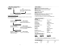
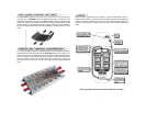
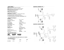
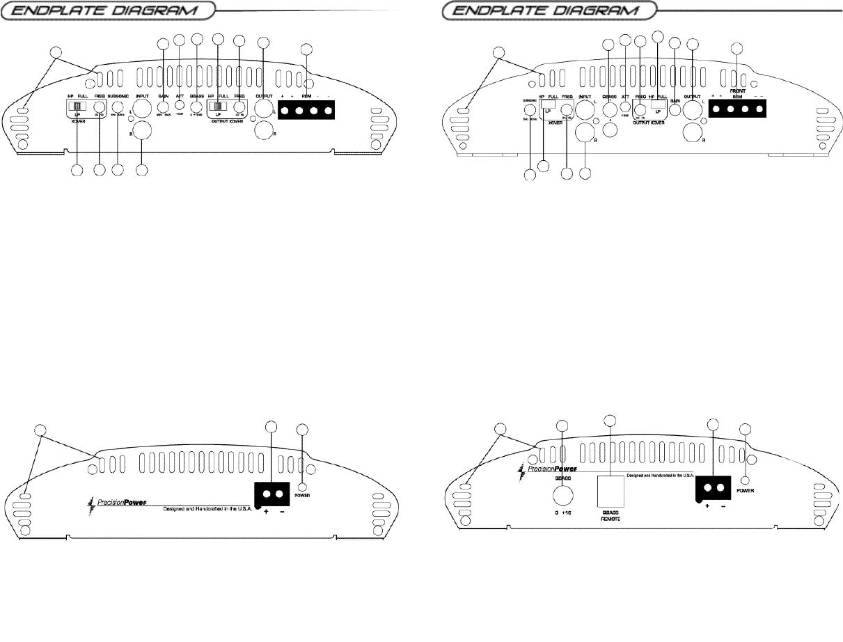
1. Cooling Plenums: Maintain a minimum 2” clearance around cooling plenums for proper amplifier
cooling.
2. HP/LP/FULL Switch: Select the desired crossover setting, HP/LP/FULLfor the speaker output
signal of the front channel.
3. Freq. Control: Move this detented control in a clockwise rotation to adjust the front crossover fre-
quency from 30Hz to 4kHz.
4. Subsonic Filter Freq. Control: Move this detented control in a clockwise rotation to adjust the
subsonic crossover frequency from 5Hz to 80Hz.
5. RCAInputs: Connect the RCAcables from the head-unit, video unit, or line driver to these RCA
connectors.
6. Gain Control: Use this control to match the output level of the source unit to the input of the amplifier.
7. -12dB: For use with high level inputs (4V up to 12V). Push this switch in to attenuate the input by
12dB.
8. QBASS™ 0 to +12dB
9. Output Crossover HP/LP/FULLSwitch: Select the desired crossover setting, HP/LP/FULLfor
the output signal of the RCAoutput.
10. Output Crossover Freq. Control: Move this detented control in a clockwise rotation to adjust
the front crossover frequency from 30Hz to 4kHz.
11. RCAOutputs: RCAoutputs provide HP/LP/Full; 30-4KHz to another amplifier.
12. Speaker Output Connections: Plug the Speaker PowerLock™ connector in here.
1. Cooling Plenums: Maintain a minimum 2” clearance around cooling plenums for proper amplifier
cooling.
2. Subsonic Filter Freq. Control: Move this detented control in a clockwise rotation to adjust the
front crossover frequency from 5Hz to 80Hz.
3. HP/LP/FULL Switch: Select the desired crossover setting, HP/LP/FULL for the speaker output
signal of the front channel.
4. Freq. Control: Move this detented control in a clockwise rotation to adjust the front crossover fre-
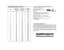
quency from 30Hz to 4kHz. (See Crossover frequency chart pg. 16)
5. RCAInputs: Connect the RCAcables from the head-unit, video unit, or line driver to these RCA
connectors.
6. QBASS 1 & QBASS 2 Freq.: Use these switches, QBASS 1 & QBASS 2 to program the QBASS
PLUS™ circuit frequency.
6. -12dB Input Attenuation: Push this switch ‘ I N ’ for high voltage input (4V-12V) capability. This button
pushed ‘ I N ’ must be used for speaker level input on common ground head-units or for high voltage line drivers.
8. Freq. Control: Move this detented control in a clockwise rotation to adjust the front crossover frequency
from 30Hz to 4kHz.
9. Output Crossover Control: HP/LP/FULL, Move this detented control in a clockwise rotation to
adjust the front crossover frequency from 30Hz to 4kHz. (See Crossover frequency chart pg. 16)
10. Gain Control: Use this control to match the output level of the source-unit to the input of the amplifier
11. RCAOutputs: Left and right RCAoutputs provide HP/LP/Full;
30-4KHz to another amplifier.
12. Speaker Output Connections: Plug the Speaker PowerLock™ connector in here.
1
2
3
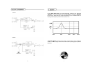
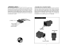
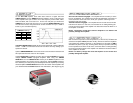
1. Thermal Management Intake/Exhaust Plenums
2. Power / Ground PowerLock: After you have securely connected your power and ground wires,
plug in the Power/GroundPowerLock connector here.
3. Power indicator: Agreen light indicates that the amplifier is on.
1. Forced Air Thermal Management Intake/Exhaust Plenums
2. QBASS PLUS™: level control up to 18dB.
3. QBASS REMOTE™ plug in: Plug in the data cable from the optional QBASS REMOTE™ dash
mount level control here. (This will bypass the amplifier’s on board QBASS™ control)
4. Power / Ground PowerLock: After you have securely connected your power and ground wires,
plug in the Power/GroundPowerLock connector here.
5. Power indicator: Agreen light indicates that the amplifier is on.
1
2
3
4
5
12