


76
INSTALLATION AND ASSEMBLY
5. SPECIAL INSTALLATION
(1) Wall inset
¶ See the descriptions in (2), (4) and (17) under “1. Installation conditions”.
* NOTE
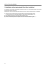
With the RM-V2550S2, the external dimensions of the system may change with changes in temperature and
humidity. In the case of embedding in a wall, make sure that you leave space as follows (both at the sides and
at the top).
2mm per row/column of screens. Example: For 4 screens (2 x 2), 4mm of space is required at the sides and
4mm at the top.
(2) Diagonal installation
¶ This system cannot be placed facing upwards or downwards and diagonally. Always place it horizontally.
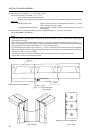
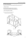
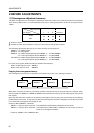
(3) Architrave processing
¶ When enclosing the screen with a frame, etc., add 15 mm
to the dimensions of the assembled screen at the top, bot-
tom, left, and right. [Fig. 3-4-53]
* Perform framing constructions after assembling the screen.
¶ If light leaks from the rear space after constructions, place
a blind plate over the rear.
(4) Upside down installation
¶ Not possible
(5) Hanging from ceiling
¶ Not possible
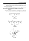
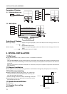
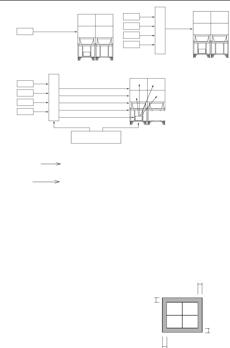
Examples of System
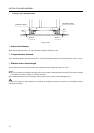
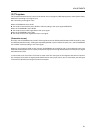
(1) Enlarged display only
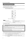
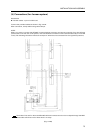
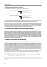
(2) Multi display
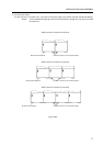
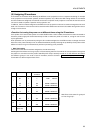
Switching of Displays
¶ Enlarged display 1 Select the signal displayed by the matrix SW, and send the signal line to the
MVP.
2 Set the MPJ input to Y/C.
¶ Multi display 1 Select the signal displayed by the matrix SW, and send the signal line of the
MPJ.
2 Set the MPJ input to C. VIDEO.
15 mm
15 mm
15 mm
15 mm
LDP
C.VIDEO
To MVP input
MVP
LDP 1
LDP 2
LDP 3
LDP 4
C.VIDEO
To MVP
input
MVP
SW or selector, etc.
LDP 1
LDP 2
LDP 3
LDP 4
Personal computer
for control
To C.VIDEO MPJ input
To C.VIDEO MPJ input
To C.VIDEO MPJ input
To C.VIDEO MPJ input
To C.VIDEO MVP input
MVP
RS-232C RS-232C
To MVP
To each MPJ
Y/C input
Matrix SW
[Fig. 3-4-53]