


75
INSTALLATION AND ASSEMBLY
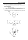
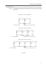
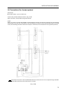
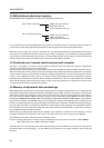
(5) Connections (for 4 screen system)
Accessories
¶ Interlock cables 6-pin mini-DIN cord
Connect the provided cables as shown in Fig. 3-4-52.
After connection, clamp cables using cable clamps.
NOTE
When you want to connect the RS-232C communications connector and remote controller from the leftmost
position seen from the rear of the system, invert the IN/OUT connections of the interlock cables (6-pin mini-DIN
cord). (The following illustration shows an example in which the are connected from the rightmost position.)
The broken lines are for when the RS-232C cable and remote control unit are relayed through the MVP.
The double solid lines are for when there is no relay.
[Fig. 3-4-52]