


70
INSTALLATION AND ASSEMBLY
12-screen assembly (work requires at least 4 persons)
1) First make a 9-screen assembly (i.e. the assembly consisting of all of the screens other than the rightmost
column made up of screens 4, 8 and =) and mount on cabinets.
(See the method for the 9-screen assembly)
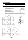
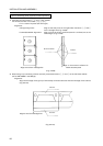
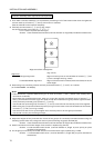
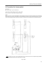
2) Vertically connect screens 4, 8 and = (Fig. 3-4-47).
You should connect in the order = + 8, = 8 + 4.
Fix in a total of 4 places (left and right)
Screws: Cross-recessed small screws (nominal diameter 4, length 25) (included as accessories)
Align so as to form a straight line
(Fig. 3-4-47)
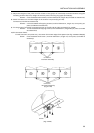
4) Adjust the heights of the joints and tilts of each of the groups of 3 vertically connected screens using the
following screws. After this, realign the vertical joints (removing any gaps) (see P52 [5]).
Screws: Cross-recessed small screws (nominal diameter 6, length 10) (included as accessories)
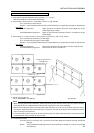
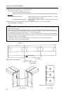
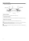
5) Attach connectors to the lower edges of the screens in 6 places (Fig. 3-4-45).
Screws: 2 cross-recessed small screws (nominal diameter 4, length 10, cone point) per place
(included as accessories)
6) Fix the groups of vertically connected screens on the left and the right (4 places) (Fig. 3-4-46).
Screws: 1 cross-recessed small screw (nominal diameter 4, length 25) per place (included as
accessories)
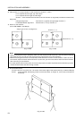
Alignment
Left/right alignment: Align so that the joints on the left sides of screens 8, 4 and
= form a straight line (Fig. 3-4-47).
Forward/backward alignment: Align so that the screen surfaces (wrench surfaces) are at the
same height.
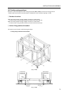
3) Mount the group consisting of the 3 vertically connected screens 4, 8 and = on a cabinet.
(as for RM-V2550S - see P50 [3])
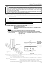
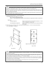
Notes
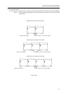
* There should be a position-determining pin in each of screens 7 and - (which have already been
mounted on a cabinet).
Since these pins protrude about 6mm, when you mount the vertically connected group of screens 4 , 8
and =, you should at first leave a gap of at least around 10mm between this group and the right-hand side
of the previously mounted group (screens 4, 8 and =).
You should then push the group of screens 4, 8 and = to the left until the vertical joints come together.
When doing this, you should make sure that the pins go into the holes in the left-hand sides of the frames
of screens 4, 8 and = as in Fig. 3-4-43b.
You will then be able to line up the heights of the vertical joints on the two groups of screens.
You should not carry out the fixing work yet.