


62
INSTALLATION AND ASSEMBLY
Notes
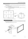
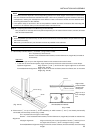
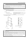
* It may be hard to push in the pins, in which case you may tap gently with a hammer.
However, hitting a pin too hard could knock the frame out of shape. Please take due care.
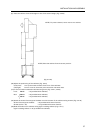
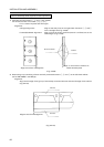
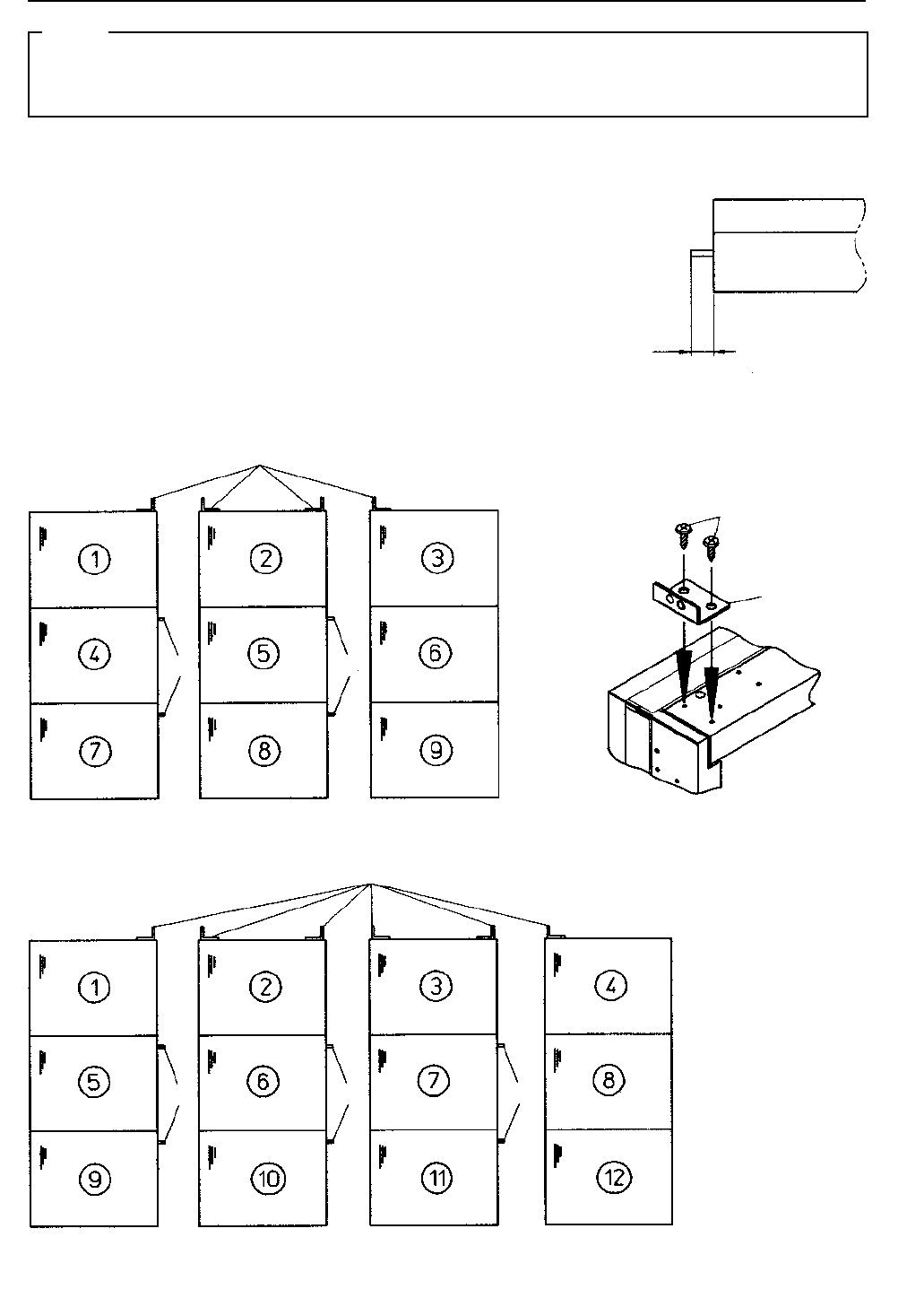
When a pin has been pushed in properly, it will stick out 6mm (Fig. 3-4-30).
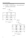
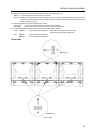
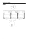
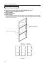
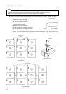
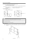
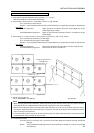
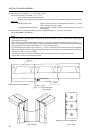
¶ Attach connectors (included as accessories) in the places shown (Fig. 3-4-29a, 3-4-29b, 3-4-29c).
9-screen system: 4 places
Right side of top edge of screen 1
Left and right sides of top edge of screen 2
Left side of top edge of screen 3
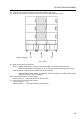
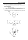
12-screen system: 6 places
Right side of top edge of screen 1
Left and right sides of top edge of screen 2
Left and right sides of top edge of screen 3
Left side of top edge of screen 4
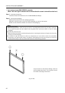
Screws: 2 cross-recessed self-tapping screws (nominal diameter 4, length 10, cone point) per
connector (included as accessories)
9-screen system
Connectors
Pins
Pins
(Fig. 3-4-29a)
Connectors
Pins
Pins
Pins
Screws
(Fig. 3-4-29c)
(Fig. 3-4-30)
Screen surface
(Fig. 3-4-29b)
12-screen system
Connectors
6mm