


18
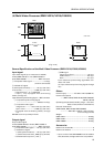
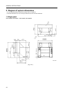
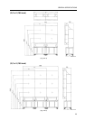
GENERAL SPECIFICATIONS
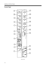
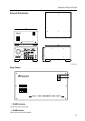
~ AC INLET
Connects the power cord to the unit.
! FUSE
Use only a fuse with the specified capacity.
Unplug the power cord before replacing the fuse.
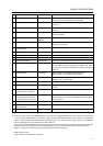
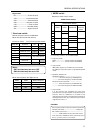
@~% V OUT connectors 1 to 4
These video output connectors output enlarged
video image signals for the 4 screens.
VBS/G ...... Output terminal of the composite video
signal or the G signal of RGB separate
signals. (Also outputs the G On Sync
signal while it outputs the G signal.)
Y/B ........... Output terminal of the Y signal or the
B signal of RGB separate signals.
C/R ........... Output terminal of the C signal or the
R signal of RGB separate signals.
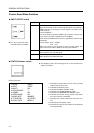
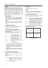
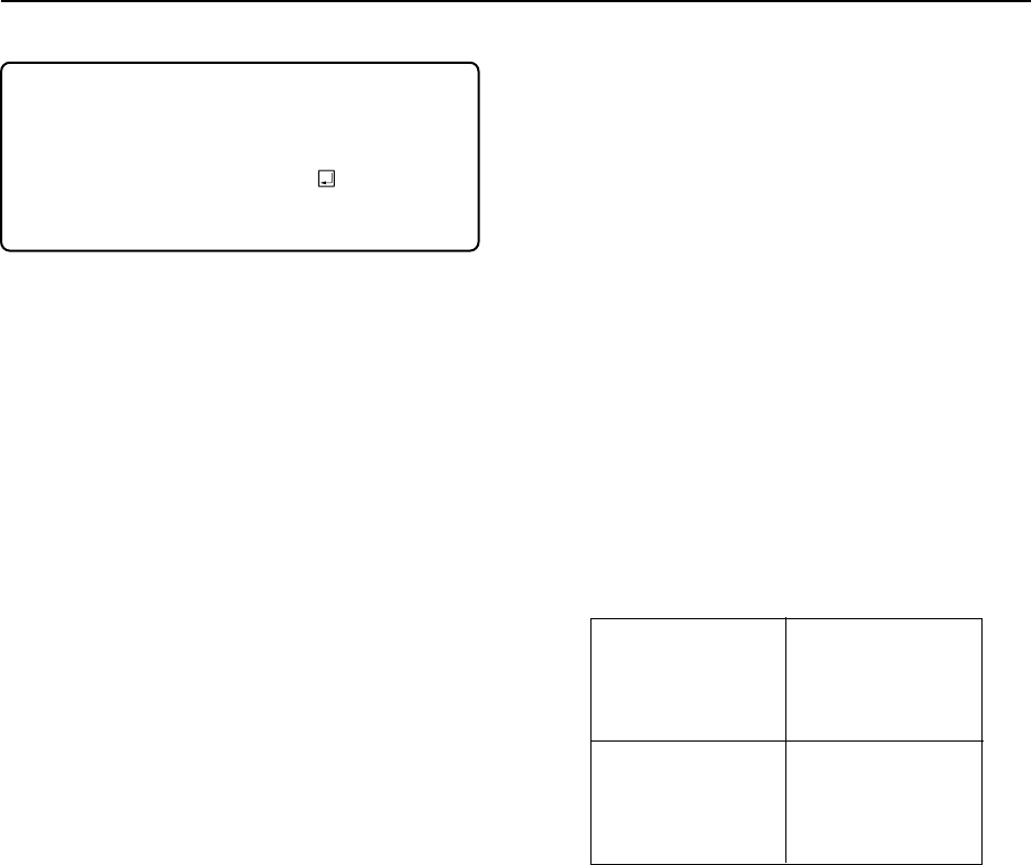
The correspondence between these outputs and
a 4 displays is shown below.
CAUTION:
MVP has each separete position data in PAL and
NTSC. When a mode is changed between PAL and
NTSC, a video image position is initialized to data that
was preserved with each mode before. Do so that you
preserve adjustable data with &W1 without fail, in
the case that a mode is changed after video image
position adjustment. (Refer to &W command)
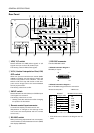
9 Reset button
Press this button to reset the system. After the
button is pressed, the system enters the manual
mode. In manual mode, this unit can be controlled
using the rear panel switches, without using a
computer.
When the reset button is pressed, this unit
functions in the modes selected by the rear panel
switches.
0 COMB cable connector
Connects the interlock cable (cord with 6P mini-
DIN plugs) provided with the display.
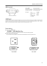
- OPTION video input connectors
These input connectors are used when an option
board is installed.
When the RMD-V3020 variable scan board is used,
their functions operate as shown below.
G .................... Input terminal for the G signal
of RGB separate signals.
B .................... Input terminal for the B signal
of RGB separate signals.
R .................... Input terminal for the R signal
of RGB separate signals.
H/CS .............. Input terminal for the H sync or
C SYNC signal.
V .................... V sync input terminal.
• As the NEC PC-9800
®
, IBM PC and DOS/V (VGA)
computers use H/V separate sync signals, their
sync signals should be connected to both the H/
CS and V connectors. H and CS use a common
connector.
• Macintosh
®
computers use the CS sync signal,
which should be connected to the H/CS
connector.
= V IN (video) input connectors
These connectors receive video data (V IN signal
images).
Apply V IN (Video) input signals to these
connectors.
VBS/Y ...... Input terminal for the composite video
signal or the Y signal of Y/C separate
signals.
C ............... Input terminal for the C signal of Y/C
separate signals.
4 displays (front view)
V OUT1
V OUT2
V OUT3 V OUT4