


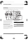
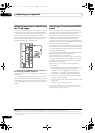

Connecting your equipment
03
38
en
Switching components on and off using
the 12 volt trigger
You can connect components in your system (such as a
screen or projector) to this receiver so that they switch on
or off using 12 volt triggers when you select an input
function. However, you must specify which input
functions switch on the trigger using the The Input Setup
menu on page 44. Note that this will only work with
components that have a standby mode.
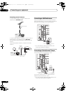
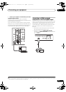
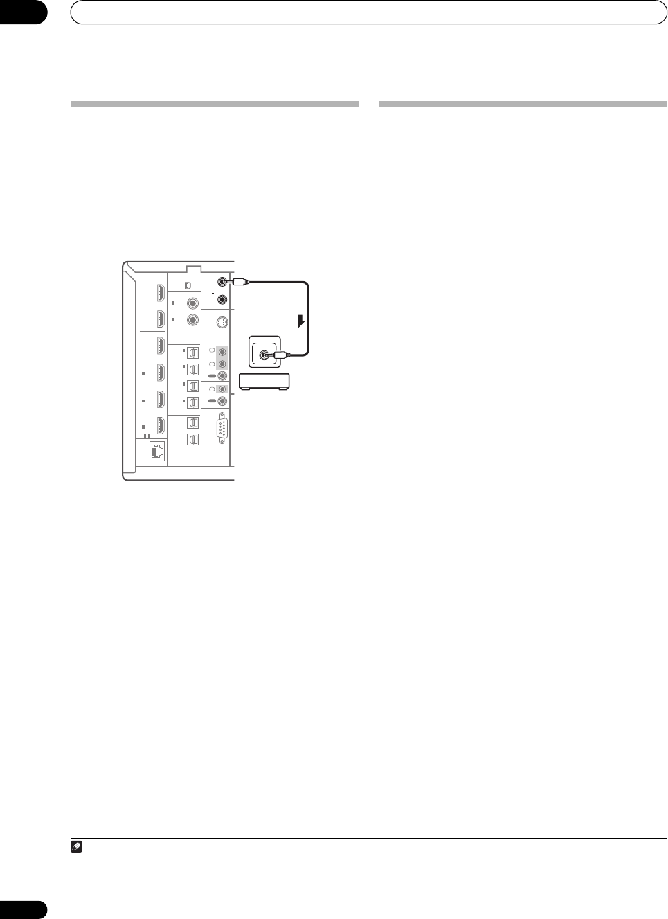
1
• Connect the
12 V TRIGGER
jack of this receiver to
the 12 V trigger of another component.
Use a cable with a mono mini-plug on each end for the
connection.
•The tr igger maximum power is DC OUT 12 V/50 mA.
After you’ve specified the input functions that will switch
on the trigger, you’ll be able to switch the component on
or off just by pressing the input function(s) you’ve set on
page 44.
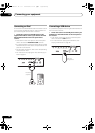
Connecting a PC for Advanced MCACC
output
When using the Acoustic Calibration EQ Professional
(see page 101) to calibrate the reverb characteristics of
your listening room, the 3D graphs of the reverb
characteristics and group delay characteristics in your
listening room (before and after calibration) can be
checked on a computer screen by connecting the
receiver to the computer and using a special application
to transfer the data. The various MCACC parameters can
also be checked on the computer.
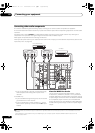
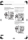
Use a commercially-available RS-232C cable to connect
the RS-232C jack on your computer to th
e 9-pin RS-232C
ja
ck on the back panel of this receiver (the cable must be
cross type, female–female).
The software to output the results is available from the
support area of the Pioneer website (http://
www.pioneerelectronics.com/PUSA/
Home+Entertainment+Custom+Install). Instructions
for using the software are also available here. If you have
any questions regarding, please contact the Customer
Support Division of Pioneer.
Please make sure your system meets the following
requirements:
•The computer must be a PC functioning with one of
the following operating systems: Microsoft
®
Windows
®
Vista Home Basic/Home Premium/
Ultimate SP1, Windows
®
XP Professional/Home
Edition SP3 or Windows
®
2000 Professional SP4.
• The monitor must have a display resolution of 800 x
600 dots (SVGA) or greater.
•The computer must be equipped with at least one RS-
232C port.
2
• System must have internet access.
Microsoft
®
, Windows
®
Vista, Windows
®
XP and Windows
®
2000 are
either registered trademarks or trademarks of Microsoft Corporation in
the United States and/or other countries.
Note
1Triggered connections with up to two devices compatible with 12 volt triggers can be made with this receiver.
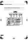
LAN
(10/100)
S
OPTICAL
RS-232C
HDMI
COAXIAL
XM
IR
CONTROL
SIRIUS
BD
IN
IN
IN
12 V
TRIGGER
IN
1
IN
2
IN
3
OUT
1
OUT
2
OUT 1
OUT 2
ASSIGNABLE
31
-
(KURO
LINK )
ASSIGNABLE
ASSIGNABLE
(CD-R)
IN
4
(VIDEO1)
IN
3
(DVR)
IN
2
(TV/SAT)
IN
1
IN
2(CD)
IN
1
(DVD)
(OUTPUT
12V
TOTAL
50 mA
MAX)
1
2
IN
1
IN
IN
2
OUT
OUT
(D
12 V
TRIGGER
(OUTPUT
12V
TOTAL
50 mA
MAX)
1
2
12 V
TRIGGER
2Laptops and other computers not equipped with an RS-232C port can be connected via USB port using a commercially available USB to
RS-232C converter cable (USB to serial converter cable). For instructions on COM port connections and settings, contact the manufacturer
of your computer.
SC-9540.book 38 ページ 2009年4月24日 金曜日 午後1時42分