


4
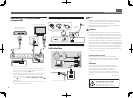
Connecting a TV and playback
components
Note
• Refer to the operating instructions in the included CD-
ROM if you wish to connect a TV or playback component
in a method other than an HDMI connection.
• Refer to the operating instructions in the included CD-
ROM for other device connections.
CAUTION
• Handle the power cord by the plug part. Do not pull out
the plug by tugging the cord, and never touch the power
cord when your hands are wet, as this could cause a short
circuit or electric shock. Do not place the unit, a piece of
furniture, or other object on the power cord or pinch the
cord in any other way. Never make a knot in the cord or tie
it with other cables. The power cords should be routed so
that they are not likely to be stepped on. A damaged power
cord can cause a fire or give you an electric shock. Check
the power cord once in a while. If you find it damaged,
ask your nearest Pioneer authorized independent service
company for a replacement.
Connecting up (continued)
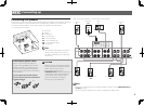
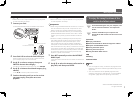
Connecting antennas
ANTENNA
AM LOOP FM UNBAL 75
ANTENNA
AM LOOP FM UNBAL 75
1
4
5
2
3
ab c
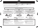
Connecting to the network through
LAN interface
LAN
(
10/100
)
LAN
(
10/100
)
WAN
3
2
1
LAN
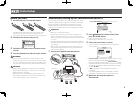
VENTILATION CAUTION
When installing this unit, make sure to leave space
around the unit for ventilation to improve heat radiation
(at least 20 cm at top, 10 cm at rear, and 20 cm at each
side).
WARNING
Slots and openings in the cabinet are provided for
ventilation to ensure reliable operation of the product,
and to protect it from overheating. To prevent fire
hazard, the openings should never be blocked or
covered with items (such as newspapers, table-cloths,
curtains) or by operating the equipment on thick carpet
or a bed.
D3-4-2-1-7b*_A1_En
• If the TV does not support the HDMI Audio Return Channel
function, optical digital cable (
A
) connection is required to
listen to the TV sound over the receiver.
• If the TV supports the HDMI Audio Return Channel function,
the sound of the TV is input to the receiver via the HDMI
terminal, so there is no need to connect an optical digital
cable (
A
). In this case, set
ARC
at
HDMI Setup
to
ON
l
“
HDMI Setup
”
• Please refer to the TV’s operation manual for directions on
connections and setup for the TV.
FM wire
antenna
AM loop antenna
LAN cable (sold separately)
Internet
Modem
Router
Computer
CAUTION:
HOT SURFACE. DO NOT TOUCH.
The top surface over the internal
heatsink may become hot when
operating this product continuously.
BD IN
LAN
(
COAXIAL OPTICAL
ASSIGNABLE
ASSIGNABLE
IN
1
(
DVD
)
IN
2
(
SAT/CBL
)
IN
3
(
DVR/BDR
)
IN
4
(
VIDEO
)
IN
1
(
TV
)
IN
2
(
DVR/BDR
)
IN
1
(
DVD
)
IN
2
(
SAT/CBL
)
IN
6
IN
7
IN
8
OUT 2OUT 1
(CONTROL)
BD IN
LAN
(
10/100
)
DC OUTPUT
for
WIRELESS LAN
(
OUTPUT 5 V
0.6 A MAX
)
COAXIALOPTICAL
ASSIGNABLE
ASSIGNABLE
IN
1
(
DVD
)
IN
2
(
SAT/CBL
)
IN
3
(
DVR/BDR
)
IN
4
(
VIDEO
)
IN
1
(
TV
)
IN
2
(
DVR/BDR
)
IN
1
(
DVD
)
IN
2
(
SAT/CBL
)
IN
6
IN
7
IN
8
OUT
OUT 2OUT 1
(CONTROL)
HDMI
OUT 3
(HD ZONE)
ASSIGNABLE
SELECTABLE
1
-
8
DIGITAL OUT
OPTICAL
HDMI INHDMI OUT
A
HDMI/DVI-compatible
Blu-ray DIsc player
HDMI/DVI-compatible TV