


Connecting your equipment
03
15
En
Chapter 3:
Connecting your equipment
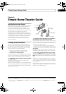
This receiver provides you with many connection possibilities, but it doesn’t have to be difficult. This page explains the
kinds of components you can connect to make up your home theater system.
Important
• Illustration shows the SC-07, however connections for the SC-05 are the same except where noted.
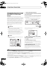
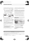
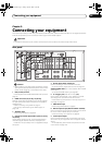
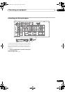
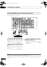
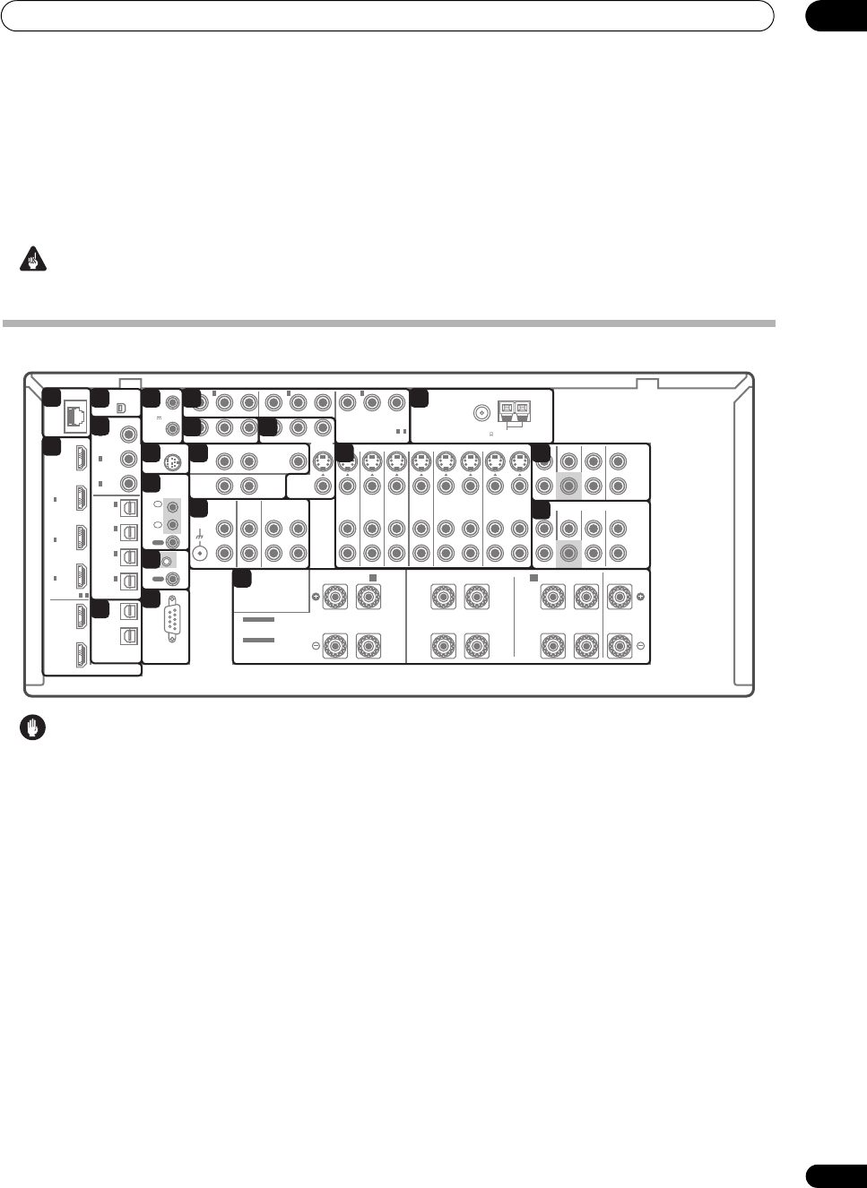
Rear panel
Caution
• Before making or changing the connections, switch
off the power and disconnect the power cord from the
power outlet. Plugging in should be the final step.
1 LAN (10/100) terminal
See Playback with HOME MEDIA GALLERY inputs on
page 73.
2 HDMI connectors (x6 (SC-07), x5 (SC-05))
Multiple inputs and one (SC-05) or two (SC-07) outputs
for high-quality audio/video connection to compatible
HDMI devices.
See Connecting using HDMI on page 17.
SC-07 only: See Switching the HDMI output on
page 100.
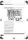
3 XM Radio input
See Using XM Radio on page 60.
4 Optical and coaxial digital audio inputs (x7 (SC-07),
x6 (SC-05))
Use for digital audio sources, including DVD players/
recorders, digital satellite receivers, CD players, etc.
See also The Input Setup menu on page 92 to assign
the inputs.
5 Optical digital audio outputs (x2)
Use for recording to a CD or MiniDisc recorder.
See Connecting digital audio sources on page 24.
ZONE3/SOURCE OUT
jack is also used for MULTI-ZONE
connections.
See MULTI-ZONE listening on page 66.
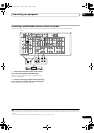
6 12 V trigger jacks
(total 50 mA max.)
(x2)
Use to switch components in your system on and off
according to the input function of the receiver.
See Switching components on and off using the 12
volt trigger on page 70.
7 SIRIUS Radio input
See Using SIRIUS Radio on page 61.
8 Remote inputs/output (
MULTI-ZONE & SOURCE
)
Use for connection to an external remote control sensor
for use in a MULTI-ZONE setup, for example.
See Connecting an IR receiver on page 69.
9 Control input/output
Use to connect other Pioneer components so that you
can control all your equipment from a single IR remote
sensor.
See Operating other Pioneer components with this
unit’s sensor on page 108.
LAN
(10/100)
DIGITAL
SPEAKERS
CAUTION:
SPEAKER IMPEDANCE 6Ω - 16Ω .
ATTENTION:
ENCEINTE D'IMPEDANCE DE 6Ω - 16Ω .
OPTICAL
RS-232C
HDMI
COAXIAL
COMPONENT VIDEO
ANTENNA
PRE OUT
MULTI CH IN
A
XM
IR
CONTROL
SIRIUS
BD
IN
IN
IN
12 V
TRIGGER
IN
1
IN
2
IN
3
OUT
1
OUT
2
SOURCE
OUT
ZONE3/
SOURCE
OUT
31
ASSIGNABLE
-
31
ASSIGNABLE
-
(HDMI
CTRL)
ASSIGNABLE
ASSIGNABLE
(CD-R)
IN
4
(VIDEO1)
IN
3
(DVR1)
IN
2
(TV/SAT)
IN
1
IN
3(DVR2)
IN
2(CD)
IN
1
(DVD)
IN
1 IN
2
(OUTPUT
12V
TOTAL
50mA
MAX)
1
2
IN
1
IN
IN
2
OUT
OUT
(DVD)
PR PB YPR PB Y
P
R PB Y
(VIDEO1)
IN
3
(VIDEO2)
R
ZONE 2 OUT
MONITOR
OUT
PHONO
IN
CD
IN
DVD
IN
TV/SAT
IN
VIDEO1
IN
VIDEO2
IN OUT
DVR1
IN OUT
DVR2
IN
OUT IN
CD-R/TAPE
SIGNAL
GND
ZONE 2
OUT
ZONE 3
OUT
VIDEO
VIDEO
S-VIDEO
FRONT CENTER
SUBWOOFER
SURROUND SURROUND BACK
FRONT CENTER
CENTER
LR
FRONT
B
LR
SURROUND BACK/
LR
SURROUND
SUBWOOFER
SURROUND SURROUND BACK
(Single)
(Single)
L
L
R
SEE INSTRUCTION
MANUAL
L
R
L
R
FM UNBAL 75 AM LOOP
SELECTABLE
VOIR LE MODE
D'EMPLOI
SELECTABLE
1
2
3
4
5
6
7
8
9
10
11
12
13
14
15
16
17
18
19
20
SC07-05.book Page 15 Friday, April 25, 2008 11:59 AM