


11
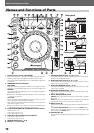
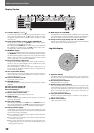
Before Operating (Names and Functions of Parts)Names and Functions of Parts
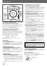
14. VINYL SPEED ADJUST TOUCH/BRAKE dial
When the JOG MODE SELECT button is set to [VINYL], this dial
determines the deceleration speed until play stops when the sur-
face of the jog dial is pressed or the PLAY/PAUSE button is pressed.
When the VINYL SPEED ADJUST TOUCH/BRAKE dial is rotated
counterclockwise, play stops quickly; when the dial is rotated clock-
wise, play decelerates more slowly before coming to a stop.
15. VINYL SPEED ADJUST RELEASE/START dial
When the JOG MODE SELECT button is set to [VINYL], this dial
determines the acceleration speed until full playback speed is reached
when the jog dial is released or the PLAY/PAUSE button is pressed.
When the VINYL SPEED ADJUST RELEASE/START dial is rotated
counterclockwise, play accelerates to full speed quickly; when the
dial is rotated clockwise, play accelerates more slowly before reach-
ing full speed.
16. JOG MODE SELECT button
VINYL mode: When the surface of the jog dial is pressed during
playback, play stops, and if the jog dial is then rotated, sound is pro-
duced in accordance with the degree of rotation.
¶ The currently set jog mode is stored in memory even when power
is turned off.
CDJ mode: The above action does not occur when the jog dial is
pressed.
17. VINYL indicator
Lights when jog mode is set to VINYL mode.
18. CDJ indicator
Lights when jog mode is set to CDJ mode.
19. TEMPO control range selector button
(TEMPO ±6/±10/±16/WIDE)
Each time this button is pressed, the tempo adjust slider’s variable
range alternates between ±6 %, ±10 %, ±16 % and WIDE.
20. MASTER TEMPO button/indicator ☞ P. 1 6
When pressed, the master tempo function alternates ON/OFF.
21. Tempo adjust slider
When moved toward the user (+ front), the track tempo increases,
and when moved away from the user (– rear), the tempo decreases.
22. Tempo reset indicator
Regardless of the position of the tempo adjust slider, this indicator
lights when the tempo adjustment is at “0” (normal tempo).
23. TEMPO RESET button
Regardless of the position of the tempo adjust slider, pressing this
button causes the tempo to be reset instantly to “0” (normal tempo).
Pressing the button once again releases the reset.
24. Jog dial display ☞ P. 12 (71 to 75)
25. Jog dial (+FWD/–REV) ☞ P. 1 6
26. Play/pause indicator
Lights during playback, and flashes during pause mode.
27. PLAY/PAUSE button (6) ☞ P. 14
28. Cue indicator ☞ P. 14
When a cue point has been set, lights except during search.
Flashes in the pause mode to slow that a new cue point can be
input.
29. CUE button
Cue point setting ☞ P. 15
Back cue ☞ P. 15
Cue point sampler ☞ P. 15
30. SEARCH buttons (1, ¡) ☞ P. 1 4
31. TRACK SEARCH buttons (4, ¢) ☞ P. 15
32. Reverse indicator (REV)
Lights when DIRECTION selector switch is set to reverse [REV].
33. DIRECTION selector switch (FWD/REV)
When set to [REV] (near side), reverse play is enabled. ☞ P. 19
34. HOT CUE REC MODE button ☞ P. 1 9
Switches the function of the HOT CUE button (record/call)
¶ Defaults to call mode when power is first turned on.
35. HOT CUE button/indicator (A, B, C) ☞ P. 19
When the indicators A, B, C light red, the hot cue point recording
mode is enabled for that point. When any of the indicators A, B, C
light green (HOT CUE point) or orange (HOT LOOP point), the re-
spective call-up mode is enabled, and if the corresponding button is
pressed, playback starts from the set hot cue (loop) point. When an
indicator is not lighted, no hot cue (loop) point has been recorded.
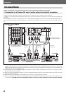
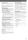
Rear Panel
36. CONTROL connector
When the accessory control cord is used to connect this connector
to the corresponding CONTROL connector on a Pioneer DJ mixer,
the DJ mixer can be used to control the CD player for fader start play
and back cue.
Also, by connecting this connector to the CONTROL connector on
another Pioneer DJ CD player, automatic relay play can be performed.
☞ P. 19
37. AUDIO OUT L, R connectors
RCA-type analog audio output jacks.
38. DIGITAL OUT connector
RCA type coaxial digital output connectors used to connect a DJ
mixer or AV amplifier, CD player, etc., equipped with digital input
connectors. The digital outputs here support all DJ and other func-
tions, but only audio data is output (without subcodes; CD graphics
are not supported).
39. POWER — OFF/_ ON switch
40. AC inlet (AC IN)
Use the accessory power cord to connect this inlet to a standard AC
power outlet.
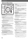
Front Panel
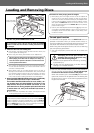
41. Memory card indicator ☞ P. 2 0
This indicator lights with a memory card is loaded and the door is
closed, and flashes during memory card access.
¶ Do not open the door or turn off power while the indicator is flash-
ing.
42. Memory card door and slot ☞ P. 2 0
43. Forced eject hole ☞ P. 1 3
44. Disc loading slot ☞ P. 1 3