


CONCEPTSYSTEM EXAMPLESCONNECTIONSPRODUCTSBLOCK DIAGRAMS
43
3
CONNECTIONS
WR-201E
CONCEPT SYSTEM EXAMPLES CONNECTIONS PRODUCTS BLOCK DIAGRAMS
42
3
CONNECTIONS
WR-201E
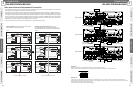
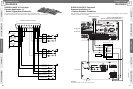
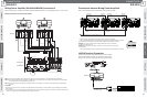
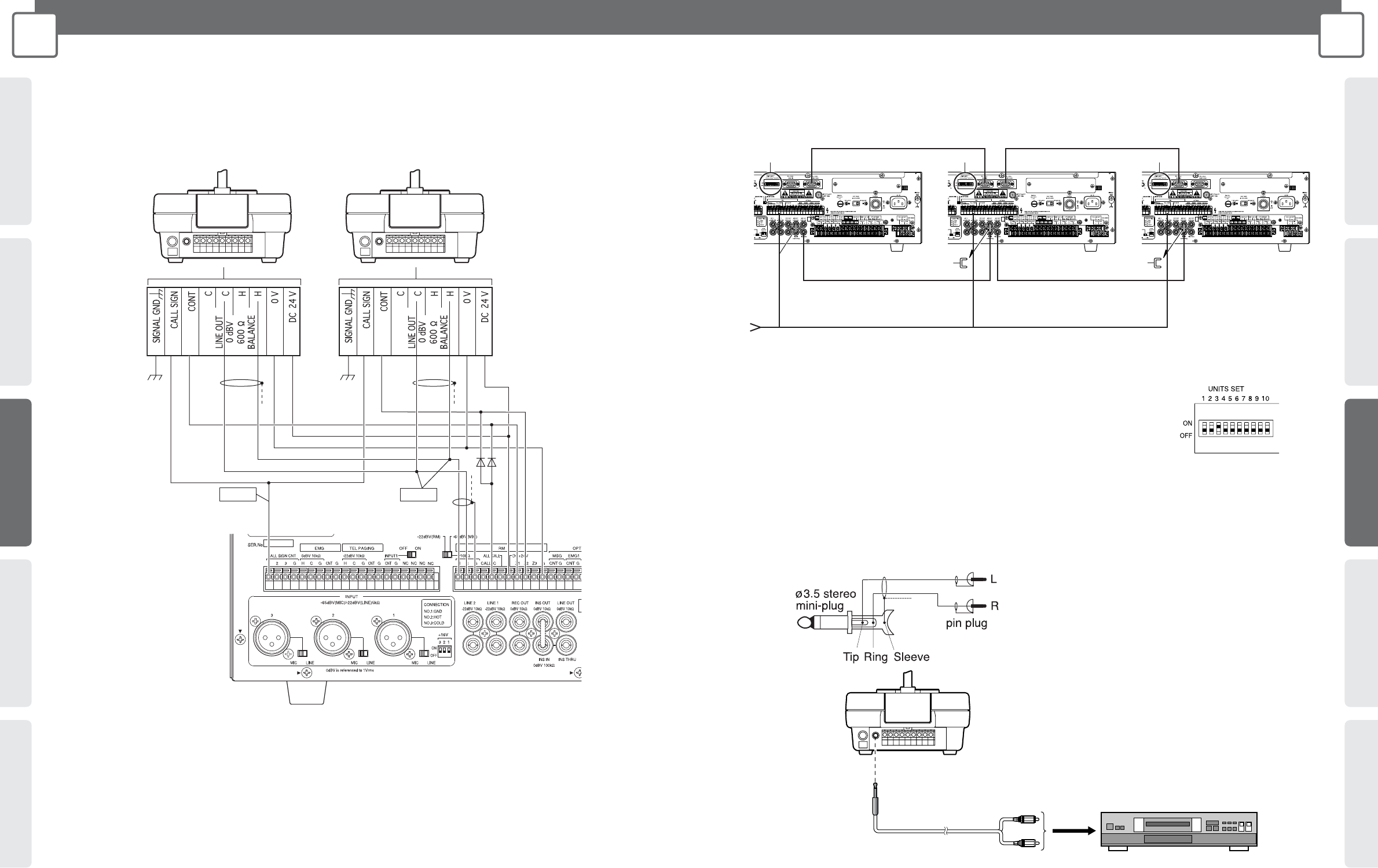
Mixing Power Amplifier (WA-MA120N/240N) Connection-2
Refer to previous page for "Mixing Power Amplifier (WA-MA120N/240N) Connection-1" and the illustration and set 1 and 2 as well.
Making connections for zone announcements
Connections between Mixing Power Amplifiers
Refer to the Operating Instructions of the Mixing Power Amplifier for details.
*1: Connect the ALL CALL BUS to be able to make all-line all-zone announcements.
Refer to the Operating Instructions of the Mixing Power Amplifier for the specifications for the cables.
*2: Set all the unit count switches for the total number of Mixing Power Amplifiers connected.
Example: Turn all "3" ON if three units, including masters and slaves, are connected.
*3: Remove the slave's short pin.
Important: Do not remove the master's short pin. If it is removed, audio will not be output.
*4: Connect INS.
Refer to the Operating Instructions of the Mixing Power Amplifier for the specifications for the cables.
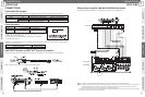
*1
Note 1 Note 2
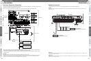
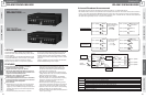
Note 1: Connect to play the Mixing Power Amplifier's call sign from the CALL SIGN button on the Remote Microphone (WR-201E).
Note 2: When the Remote Microphones (WR-201E) and (WR-201E) are connected to the same system, audio signals are mixed and heard in
all connected zones if you operate them at the same time.
Note 3: When using more than one Mixing Power Amplifiers, refer to the instructions on Connection between Mixing Power Amplifiers. (See
page 43.)
Important:
• Set the call sign volume-control on the bottom of the Remote Microphone (WR-201E) to its lowest setting to use the Mixing Power Amplifier's
built-in call sign.
*1 When using more than one Remote Microphone (WR-201E) to make announcements to each block, a reverse current inhibitor diode (forward
current 1 A or greater, peak inverse voltage 200 V or greater) is necessary.
ALL CALL
BUS THRU
Master Slave1 Slave2
INS
THRU
INS
IN
INS
THRU
INS
IN
ALL CALL
BUS IN
ALL CALL
BUS THRU
ALL CALL
BUS IN
*1
*2
*3
*3
*1
*2 *2
*3
*4*4
BC BC BC
To the CONT terminal of the Remote Microphone
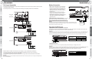
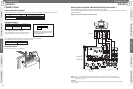
LINE IN Terminal Connection
The Remote Microphone's LINE IN terminal uses a stereo mini-jack.
Commercially available CD players are connected as shown below.
Wiring for the ø3.5 stereo mini-plug and the pin plug is shown below.
CD player
L
R
To line out
of CD player
To line in terminal
ø3.5
stereo mini-plug splits
into two pin plugs
WA-MA120N
or
WA-MA240N
WR-201E
WR-201E