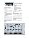
25
10
Hz
1
Hz
100
Hz
1k
Hz
10k
Hz
20
k
–15
dB
–10
dB
–5
dB
0
dB
5
dB
LCFil
Level, dB
Fre
q
uenc
y
, Hz
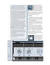
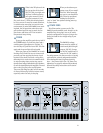
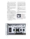
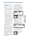
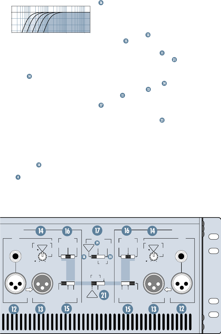
In order to match the output bandwidth
with your particular speaker system, the
M•2600 amplifier has a tunable
LOW CUT
FILTER
. The frequencies are marked along the
knob’s travel
:
• Fully counterclockwise, the frequency is
below 10Hz, effectively bypassing the filter.
• Center detent is
35Hz
and labeled
TYPICAL
,
since precious few woofers actually go
below that.
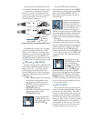
• 3/4 of the way up is labeled
STAGE MONI-
TOR, 100Hz
, perfect for stage monitors
(they seldom reproduce below 100Hz;
besides, it prevents low-frequency “leakage”
into the house).
• Fully clockwise is labeled
170Hz
.
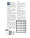
So, grab your woofer’s spec sheet and find
the low roll-off spec. Then set the M•2600’s
LOW CUT FILTER
at the same frequency.
If you do this correctly (and make sure the
meters
are happy), you’ll never again see
your woofer moving sporadically without au-
dible signal. Your system will play louder and
cleaner, and you may never blow another
woofer again!
STEREO
TYPICAL
1
CHANNEL
S
U
B
W
O
O
F
E
R
TYPICAL
35 Hz
CHANNEL
2
ON
TYPICAL
IN
IN
LOW CUT FILTER
INPUT
INPUT
CROSSOVER
SWITCHED OUTPUT
SWITCHED OUTPUT
BALANCED
OR
UNBALANCED
170 Hz
100 Hz
OFF
STAGE
MONITOR
90Hz
LOW
OUT
HIGH
OUT
THRU
LOW
OUT
HIGH
OUT
THRU
120Hz
60Hz
CROSSOVER
90Hz
120Hz
60Hz
AMP MODE
B
R
ID
G
E
D
M
O
N
O
OUTPUT APPLICATION
BALANCED
OR
UNBALANCED
LIMITER
(CH1 & CH2)
LOW OUT
(SUB WOOFER)
OFF
CH's
SUMMED
FULL
RANGE
LOW CUT FILTER
170 Hz
100 Hz
OFF
STAGE
MONITOR
S
U
B
W
O
O
F
E
R
TYPICAL
35 Hz
THRU
THRU
CROSSOVER SWITCH
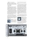
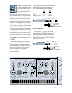
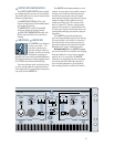
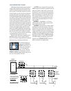
This three-way switch allows you to set the
crossover point of the internal
CROSSOVER
to either
60Hz
,
90Hz
or
120Hz
. This affects
two things:
• The
THRU
output , if the
THRU
switch is set to
LOW OUT
or
HIGH OUT.
• The
SPEAKER OUTPUTS
, if the
OUTPUT APPLICATION
switch is
set to
LOW OUT
. The amplifier then
plays the frequency range below the
crossover point.
Note: The
LOW CUT FILTER
affects
both the
THRU
outputs and the
SPEAKER
OUTPUTS
in the cases above.
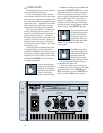
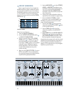
AMP MODE SWITCH
This three-way switch, along with the
OUTPUT APPLICATION
switch , determines
what kind of amplifier you want the M•2600 to
be (or not to be — what was the question?).
The
AMP MODE
switch determines the in-
put signal routing within the M•2600 amplifier.
Shipped from the factory, the switch is set to
STEREO
. This is correct for about 90% of the
applications using an amp like this (hence the
TYPICAL
indicator near it). But you may be in
the 10% bracket, requiring special input routing
within the amp.
AMP MODE
should always be configured
before operation, with the amplifier turned off.
Low Cut Filter Frequency Response


