


54
LA-140
LT-82
Design Guide
Design Guide
LA-140
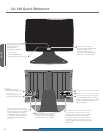
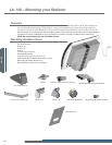
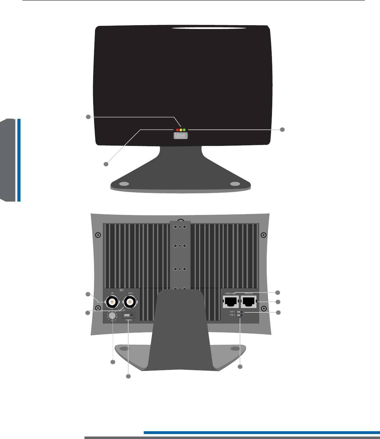
LA-140 Quick Reference
3RZHU5HG
This red LED is lit when
there is power to the radiator.
1R&RQQHFWLRQ<HOORZ
This yellow LED is lit when
the radiator is not
connected to a
transmitter or radiator.
5),QSXW
Input RF signal from a
transmitter or radiator here.
5)2XWSXW
Output RF signal to an
additional radiator here.
3RZHU,QSXW&RQQHFWSRZHUKHUH
&DUULHU3UHVHQW*UHHQ
This green LED is lit when there
is signal present to the
radiator. During normal
operation the red and green
LEDs will be continuously lit.
'HOD\&RPSHQVDWLRQ6ZLWFK
Adjust the amount of signal delay
from the radiator here. In single
radiator systems the position
of this switch does not matter,
in multiple radiator systems this
switch must be set properly.
see page 56
7HUPLQDWLRQ6ZLWFK,IWKHUHLVQR
RF being output from the RF
Output connection, this switch
must be in the “ON” position.
3RZHU2XWSXW2XWSXWSRZHUKHUH
/(',QGLFDWRU6KXWRII6ZLWFK6:
Controls LED indicators on front of
radiator. If switch is set to the “OFF”
position, LEDs will not light up on
front of radiator.
&RPSDWLELOLW\ZLWK2WKHU0DQXIDFWXUHU·V
6ZLWFK6:,IXVLQJD/LVWHQ/$
5DGLDWRUZLWKDQRWKHUPDQXIDFWXUHU·V
transmitter/modulator it is necessary
to put this switch in the “ON” position.
,03257$17$OZD\VHQVXUH6:LVLQWKH
“OFF” position when using a Listen LT-82
Transmitter.