


Danish Interpretation Systems User Manual
Manual 01 18 04438
36
Appendix
Technical appendix
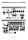
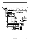
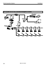
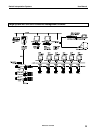
Cabling
CAT5
The DCS 6000 system uses CAT5, CAT5e or
CAT6 FTP or STP cables with screened RJ45
connectors.
EIA 568-B wiring shall be used.
It is important to use only FTP or STP
(screened) cables and screened RJ45 connectors
and not UTP cable, which is unscreened.
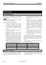
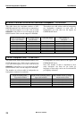
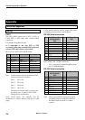
How to wire a CAT5 (EIA 568-B) Cable:
Pin
Function Connector #1
Connector #2
1 In-going + ORG/WHT ORG/WHT
2 In-going - ORG ORG
3 +48V GRN/WHT GRN/WHT
4 0V BLU BLU
5 0V BLU/WHT BLU/WHT
6 +48V GRN GRN
7 Outgoing - BRN/WHT BRN/WHT
8 Outgoing + BRN BRN
Note. If other colour codes are used then the four
pairs are connected as follows:
Pair 1: Pin 1 & 2
Pair 2: Pin 3 & 6
Pair 3: Pin 4 & 5
Pair 4: Pin 7 & 8
The phase of the pairs must be correct and
the wiring spec. as stated in CAT5 (EIA
568-B) have to be followed.
Note: CAT6 cables can normally only be
terminated in sockets (female) and not in cable
plugs.
CAT6 can thus only be used for longer cable draws
terminating in wall outlets or patch panels.
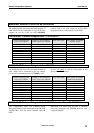
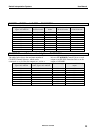
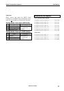
RS 232 Serial connection
Pin
RS232 on CU
6005/6010/6011
D9S
Pin
RS232 on PC
D9P
1 * 1 DCD
2 TxD 2 RxD
3 RxD 3 TxD
4 * 4 DTR
5 0V 5 0V
6 * 6 DSR
7 RTS 7 CTS
8 CTS 8 RTS
9 9 RI
Connect all pins in the connectors: Pin 1 to Pin 1,
Pin 2 to Pin 2, Pin 3 to Pin 3 and so on.
* Pin 1, 4 and 6 are connected together inside
the CU 6005/6010/6011.
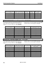
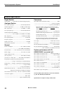
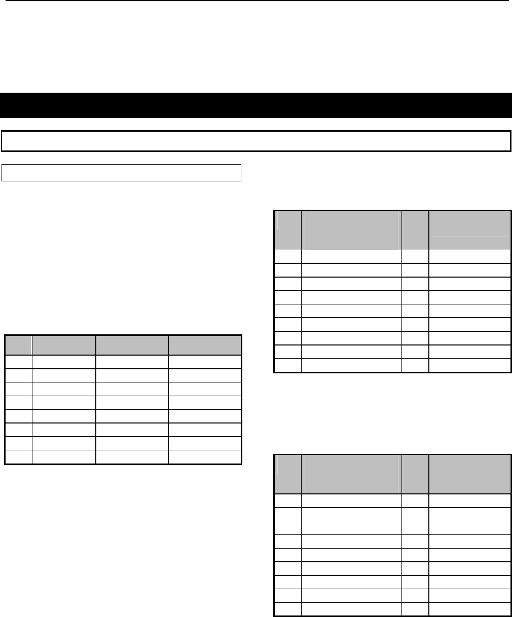
RS 422 Serial connection
Pin
RS422 on CU
6005/6010/6011
D9P
Pin
RS422 on PC
1 RXD+(B) 1
2 RXD-(A) 2
3 TXD-(A) 3
4 TXD+(B) 4
5 0V 5
6 RTS-(A) 6
7 RTS+(B) 7
8 CTS+(B) 8
9 CTS-(A) 9
Note. There is no standard for the pin layout of
the RS422. Please consult the manual for
the RS422 card in your PC or control
system.