Life Fitness Model 9100HR (REV 1 & REV 2) Treadmill
How To... INSTALL THE LIFELINK UPGRADE KIT
TOOLS REQUIRED: Standard Screwdriver, Phillips Screwdriver, Hex Key Wrench Set, Pliers, Wire Cutters,
Anti-Static Strap
WARNING: FAILURE TO OBSERVE SAFETY PROCEDURES WHEN SERVICING THIS UNIT
COULD RESULT IN INJURY FROM ELECTRICAL SHOCK
STEP 1
Turn the power off at the ON/OFF switch and unplug the unit at the wall outlet.
STEP 2
Ground yourself by positioning an anti-static strap around your wrist and attaching the other end (alligator clip or adhesive
end) to a bare metal surface on the machine frame.
(REV 1 ONLY)
STEP 3
Remove the CONNECTOR COVER under the left side of the DISPLAY
CONSOLE by removing the four screws with a Phillips screwdriver and
unplug the 4 and 10-pin CONNECTORS to the DISPLAY CONSOLE.
STEP 4
Remove the DISPLAY CONSOLE by removing the four allen bolts and
washers securing the DISPLAY CONSOLE to the HANDRAILS.
HINT: FOR EASIER REMOVAL, LOOSEN THE THREE SCREWS
HOLDING THE HANDLEBAR TO THE RIGHT SIDE HANDRAIL.
Remove the eight Phillips screws securing the console pan to the faceplate.
Remove the LIFEPULSE ASSEMBLY by removing the four screws and
unplugging the 7-PIN CONNECTOR and the ground strap. Remove the ELECTRONIC BOARD from the faceplate by removing
the eight screws and unplugging the RIBBON CABLE and STOP SWITCH CABLE.
STEP 5
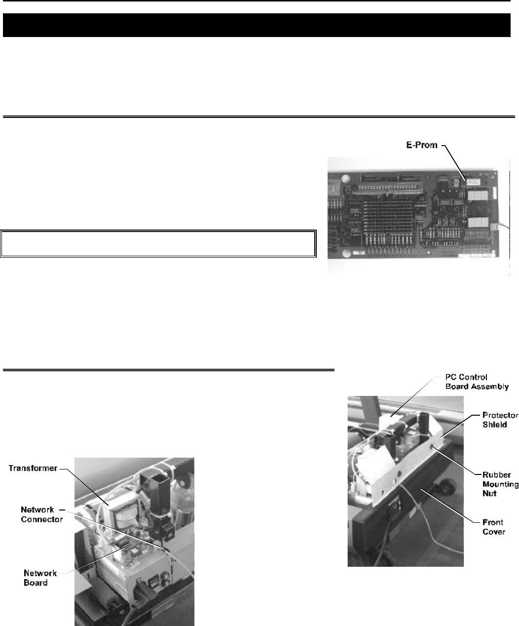
NOTE THE ORIENTATION OF E-PROM BY THE U-NOTCH.
Remove and replace the E-PROM ( U1 ) with the E-PROM supplied in the upgrade kit. Return the DISPLAY CONSOLE to its
proper position by reversing Steps 3 and 4.
STEP 6
Remove the four screws securing the MOTOR COVER in place and set the
MOTOR COVER aside.
STEP 7
Pull out the two RUBBER MOUNTING NUTS holding the FRONT PROTECTOR
SHIELD in position and remove it.
STEP 8
Remove the FRONT COVER by
removing the four screws
securing it in place.
STEP 9
Remove the two screws
securing the TRANSFORMER
to the POWER BOX, lift the
TRANSFORMER off and secure
the bracket supplied in the
upgrade kit with the two screws
to the same holes. To ensure the NETWORK BOARD fits, remove the 3/16
allen bolt that holds the POWER BOX to the FRAME and replace it with the
allen screw supplied in the upgrade kit. Slide the NETWORK BOARD
(connector facing the front) on top of THE POWER BOX and secure it to the
four existing holes with the four screws supplied in the upgrade kit. Take
the TRANSFORMER and secure to the top of the bracket with the two screws supplied in the upgrade kit.


