


P
P
r
r
o
o
d
d
u
u
c
c
t
t
F
F
e
e
a
a
t
t
u
u
r
r
e
e
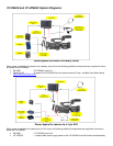
The VC-P840U provides a direct video signal connection between the JVC’s HD studio Viewfinder (VF-HP840U) and the
GY-HD250U/GY-HD200UB. This cable carries the camera’s RGB, CMP or a Y signal depending on the Camera’s VF
menu setting. The Tally and Preview signal is sent from the camera to the VF-HP840U via serial communication. This
cable does not provide power to the camcorder. It is approximately 2ft long.
U
U
s
s
e
e
r
r
B
B
e
e
n
n
e
e
f
f
i
i
t
t
This cable gives the Studio System Integrator the flexibility of using the VF-HP840U in studio applications that do not use
the studio sled (KA-HD250U); such as when a third party CCU manufactured by Telecast Fiber or Camplex is used.
Owners of the GY-HD250U and GY-HD200UB also have the choice of using the high definition VF-HP840U in non studio
applications that require a viewfinder with built in features such as safety markers, focus assist, and zebras in non studio
applications that require critical focus and VF functionality.
Required Camcorder and VF-HP840U settings
When using this cable:
• Set the GY-HD250U/GY-HD200U(B) Camera’s “VF Signal” in the “LCD/VF” menu group to “COMPONENT”.
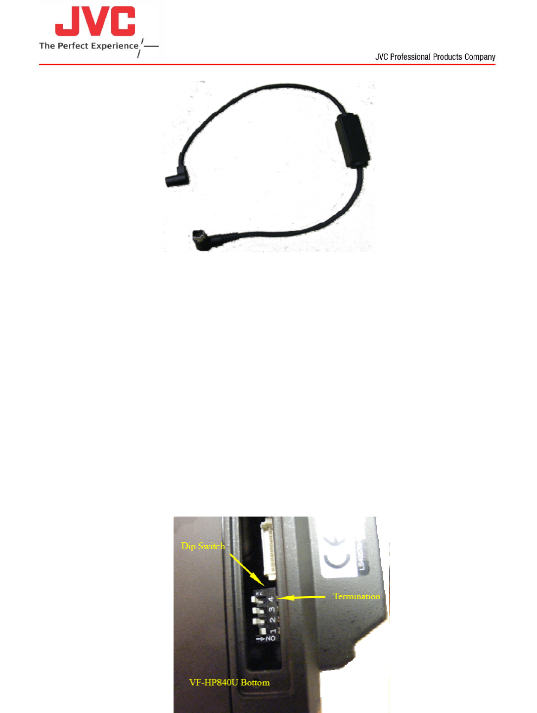
• Set the VF-HP840U’s Dip Switch4 to “OFF”. This terminates the video inputted into the studio Viewfinder with 75
ohms.
Dip switch is located on the bottom of the VF-HP840U under a cover plate. Remove two screws from cover plate and take
cover off to expose dip switch
Product Information Manual
VC-P840U
Cable