


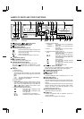
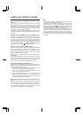
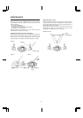
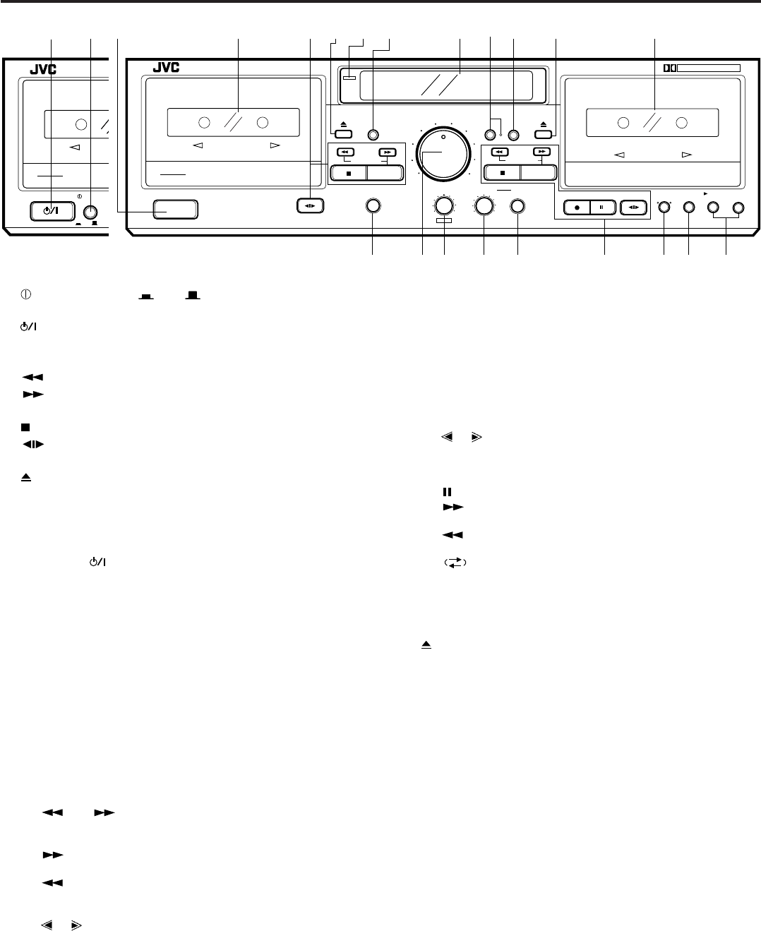
NAMES OF PARTS AND THEIR FUNCTIONS
1 POWER switch ( ON OFF) (B version)
POWER switch (On/Standby) (J version)
2
switch (STANDBY/ON) (B version)
3 Cassette holder (deck A)
4 Cassette operation buttons (deck A)
: Press to wind the tape quickly from right to left.
: Press to wind the tape quickly from left to right.
PLAY : Press to play the tape.
(stop) : Press to stop the tape.
(direction)
: Press to change the direction of tape travel.
5
(eject) button (deck A)
6 Power STANDBY indicator
Lights when in the power standby mode.
7 COUNTER RESET button (deck A)
Press this button to set the digital counter to ‘‘00 00’’.
Even if the
(STANDBY/ON) or POWER switch is set to
STANDBY, the counter value at that time is stored in
memory.
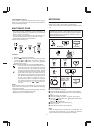
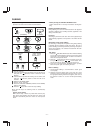
8 Indicators
1 DDRP indicator
2 Peak level indicator
These indicators light according to the level of the signal
being recorded or the level of the signal recorded on the
tape.
Note:
0 dB : IEC (DIN) STANDARD LEVEL (250 nWb/m)
0 VU : Signal level at 160 nWb/m
3 HX PRO indicator
4 Digital counter
The counter reading increases while the tape is running
from left to right and decreases when it is running from
right to left. In the Multi Music Scan mode when the
(or ) button is pressed, the number of tunes
which will be skipped is displayed.
5 Mechanism mode indicators (deck A)
: This lights when rewinding the tape
from left to right.
: This lights when rewinding the tape
from right to left.
PLAY : This lights when in the playback.
, : Indicates the direction of tape travel.
6 Dubbing mode indicators
‘‘DUBBING >’’ : Lights when in the normal-speed dub-
bing mode.
‘‘DUBBING >>’’ : Lights when in the high-speed dub-
bing mode.
7 CONT : Lights when the unit is in the continu-
ous play mode.
8 Mechanism mode indicators (deck B)
PLAY : Lights when the unit is in the playback
and record modes.
, : Indicates the direction of tape travel.
REC : Lights when the unit is in the record
and record-pause modes; blinks dur-
ing record muting.
: Pause indicator
: This lights when rewinding the tape
from left to right.
: This lights when rewinding the tape
from right to left.
9
: Indicates reverse mode.
9 COMPU CAL button and indicator
Press this button to automatically set the recording charac-
teristics with the COMPU CAL function. (See page 9.)
0 COUNTER RESET button (deck B)
q
(eject) button (deck B)
w Cassette holder (deck B)
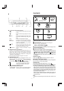
e PHONES jack
Connects headphones (with an impedance of 8 Ω to1kΩ).
r INPUT LEVEL control
t PITCH CONTROL (deck A)
Varies the tape speed in deck A in the range of about ±10%.
However, it cannot change the tape speed in the high-speed
dubbing.
Turning it counterclockwise toward ‘‘SLOW’’ causes the tape
speed to decrease while turning clockwise toward ‘‘FAST’’
causes it to increase. The center click position is for the
standard speed. (See page 8.)
y Mixing microphone level control
Adjusts the microphone input level.
u MIX MIC jack
Connects a microphone (with an impedance of 600 Ω to
10 kΩ) to this jack.
Sounds from the microphone are monaural.
12
STANDBY / ON
POWER
REC/REC MUTE
PAUSE
MUSIC SCAN
COUNTER RESET
COMPU CAL
MUSIC SCAN
COUNTER RESET
PHONES
MIX LEVEL
MIC
PITCH CONTROL
MIN
MAX
SLOW FAST
DECK A
DOLBY NR
REVERSE
MODE
A B SYNCHRODUBBING
B
C
NORM SPEEDHIGH SPEED
PLAY
PLAY
MIN
MAX
1
2
5
3
4
6
INPUT LEVEL
MIN
MAX
1
2
5
3
4
6
7
8
9
INPUT LEVEL
TD-W354
ON
OFF
DOUBLE CASSETTE DECK
DOLBY B-C NR HX PRO
AUTO REVERSE
COMPU CALIBRATION
B
REC/PLAYBACK
PITCH CONTROL
A
PLAYBACK
AUTO REVERSE
COMPULINK
Component
STANDBY
POWER
REC/REC MUTE
PAUSE
MUSIC SCAN
COUNTER RESET
COMPU CAL
MUSIC SCAN
COUNTER RESET
PHONES
MIX LEVEL
MIC
PITCH CONTROL
MIN
MAX
SLOW FAST
DECK A
DOLBY NR
REVERSE
MODE
A B SYNCHRODUBBING
B
C
NORM SPEEDHIGH SPEED
PLAY
PLAY
MIN
MAX
1
2
5
3
4
6
INPUT LEVEL
MIN
MAX
1
2
5
3
4
6
7
8
9
INPUT LEVEL
TD-W354
DOUBLE CASSETTE DECK
DOLBY B-C NR HX PRO
AUTO REVERSE
COMPU CALIBRATION
B
REC/PLAYBACK
PITCH CONTROL
A
PLAYBACK
AUTO REVERSE
COMPULINK
Component
3456780q w
a
po
i
u
y
rte
9
1
STANDBY
(B version) (J version)
–6–
id8/i10371/ 09/23/99 Page 6