


3
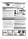
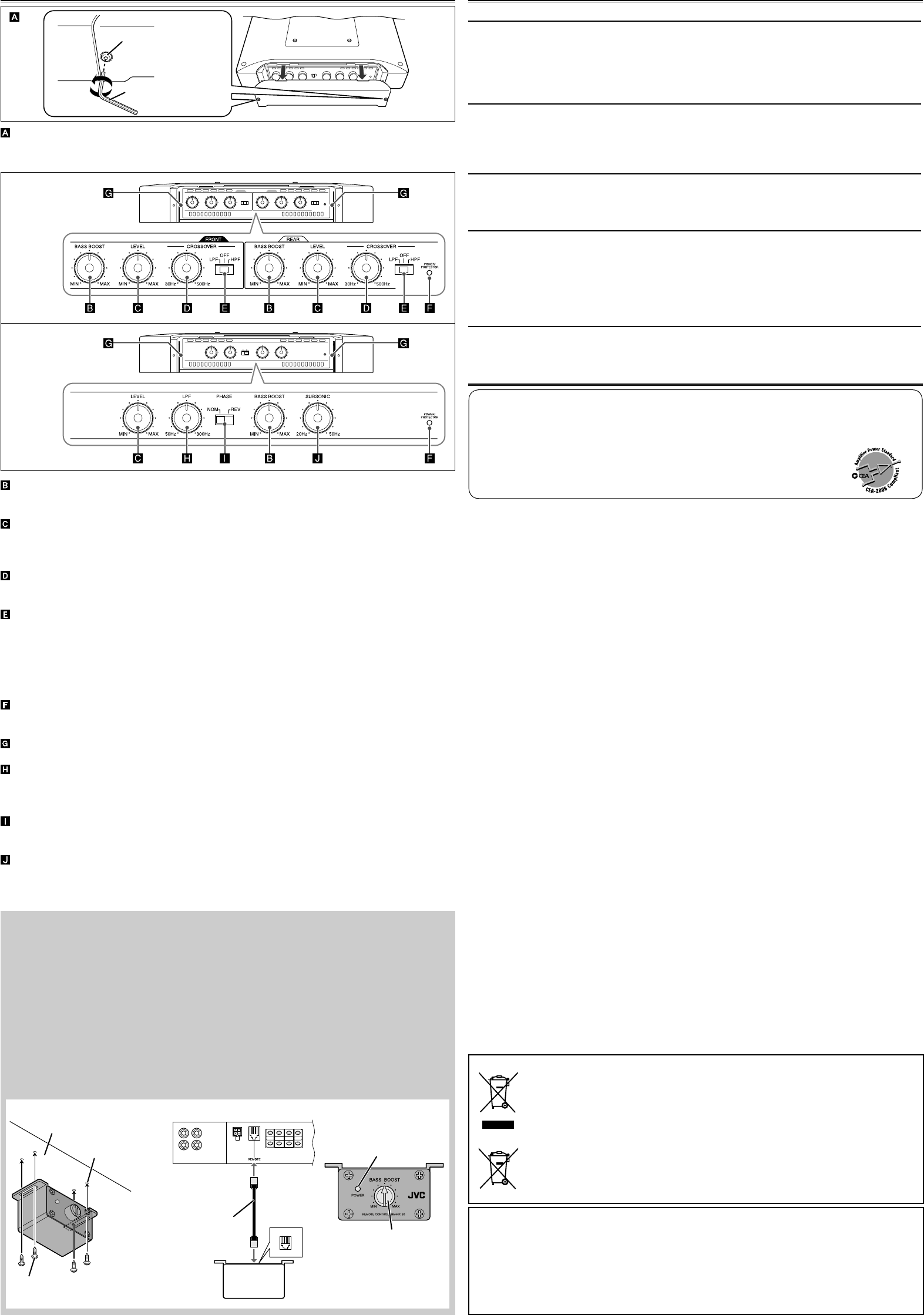
KS-AR9001D only
Wired remote control unit: RM-RK130 (purchased separately)
Using JVC’s wired remote control unit: RM-RK130 (purchased separately), you can adjust the
bass boost in your seat without adjusting the BASS BOOST controller on the amplifier (see
“CONTROLS”).
Note
Set the BASS BOOST controller on the amplifier to MIN when you use RM-RK130.
A Mount RM-RK130 on a firm surface, such as under the dashboard.
B Connect RM-RK130 to the REMOTE terminal on the amplifier with the remote cord
provided for RM-RK130.
C RM-RK130 boosts the 45 Hz frequency within the range of 0 dB to +18 dB. Adjust the level
while listening to the sound.
• The POWER lamp lights in green while RM-RK130 is turned on.
TROUBLESHOOTING
For more details, consult your JVC car audio dealer.
The POWER/PROTECTOR lamp does not light.
• Change the fuses if the current one is blown.
• Connect the ground lead securely to a metal part of the car.
• Turn on the equipment connected to this unit.
• Use a relay if your system employs too many amplifiers.
• Confirm the battery voltage (11 V to 16 V).
The POWER/PROTECTOR lamp lights in red and/or the unit heats up abnormally.
• Use the speakers of suitable impedance.
• Correct the speaker wirings if they are short-circuited.
• Make the speaker wirings away from the power cord to prevent DC offset error.
• Leave the unit turned off for a while to cool it down.
No sound is heard.
• Confirm the connections for power supply (see “POWER SUPPLY” on page 1).
• Connect RCA pin cords to the INPUT jacks, or the speaker input connector to the HIGH INPUT
terminal.
Alternator noise is heard.
• Keep the power cords away from the RCA pin cords.
• Keep the RCA pin cords away from other electrical cables in the car.
• Connect the ground lead securely to a metal part of the car.
• Make sure the negative speaker leads do not touch the car chassis.
• Replace the plugs or use plugs with load resistors.
• Connect a bypass capacitor across the accessory switches (horn, fan, etc.).
Noise is made when you connect the unit to an AM tuner.
• Move the speaker and power cords away from the antenna lead.
SPECIFICATIONS
Power Output KS-AR9004:
• Normal Mode: 100 W RMS x 4 channels at 4 Ω and ≤ 1% THD + N
KS-AR9001D:
• Normal Mode: 250 W RMS x 1 channel at 4 Ω and ≤ 1% THD + N
Signal-to-Noise Ratio KS-AR9004: 80 dBA (reference: 1 W into 4 Ω)
KS-AR9001D: 60 dBA (reference: 1 W into 4 Ω)
Power Output KS-AR9004:
• Normal Mode: 120 W RMS x 4 channels at 2 Ω and ≤ 1% THD + N
• Bridge Mode: 240 W RMS x 2 channels at 4 Ω and ≤ 1% THD + N
KS-AR9001D:
500 W RMS x 1 channel at 2 Ω and ≤ 1% THD + N
1 000 W RMS x 1 channel at 1 Ω and ≤ 1% THD + N
Maximum Power Output KS-AR9004: 800 W (400 W x 2)
KS-AR9001D: 1 200 W
Load Impedance KS-AR9004: 4 Ω (2 Ω to 8 Ω allowance)
4 Ω (4 Ω to 8 Ω allowance) (Bridge Mode)
KS-AR9001D: 4 Ω (1 Ω to 8 Ω allowance)
Frequency Response KS-AR9004: 5 Hz to 50 kHz*
1
(+0, –3 dB)
*
1
Subsonic filter cuts off extremely low frequency signals less than
20 Hz.
KS-AR9001D: 20 Hz to 300 Hz*
2
(+0, –3 dB)
*
2
Subsonic filter cuts off extremely low frequency signals. (The cutoff
frequency is adjustable within the range of 20 Hz to 50 Hz.)
Input Sensitivity/Impedance 2 V/45 kΩ (0.3 V to 6 V, variable)
Distortion KS-AR9004: Less than 0.04% (at 1 kHz)
KS-AR9001D: Less than 0.1% (at 100 Hz)
Power Requirement DC 14.4 V (11 V to 16 V allowance)
Grounding system Negative ground
Dimensions (W×H×D) 360 mm × 60 mm × 245 mm (14
3
/16 inch × 2
3
/8 inch × 9
11
/16 inch)
Mass (approx.) KS-AR9004: 4.60 kg (10.15 lbs.)
KS-AR9001D: 4.92 kg (10.85 lbs.)
Accessories Speaker input connector
KS-AR9004: 4P × 2
KS-AR9001D: 4P × 1
Screw—Dia. 4 mm (
3
/16 inch) × 20 mm (
13
/16 inch) × 4
Hex wrench
4 mm × 1
3 mm × 1
2.5 mm × 1
Spacer × 4
Bracket × 2
Hex screw—M4 × 12 mm (
1
/2 inch) × 6
Design and specifications are subject to change without notice.
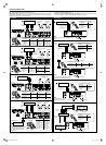
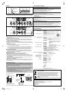
BASS BOOST controller
Turning this boosts the 45 Hz frequency within the range of 0 dB to +18 dB. Adjust the level
while listening to the sound. This controller is preset to MIN when the unit is shipped.
Input LEVEL controller
The input level can be adjusted with this controller when this unit is connected to other
source equipment. Adjust the level while listening to the sound. This controller is preset to
MIN when the unit is shipped.
CROSSOVER frequency controller
Turning this adjusts the cutoff frequency within the range of 30 Hz to 500 Hz. Adjust the level
while listening to the sound. This controller is preset to 30 Hz when the unit is shipped.
CROSSOVER filter switch
OFF: Normally, set to this position. The switch is preset to this position when the unit is
shipped.
LPF: Set to this position when you want to turn on the LPF (Low-Pass Filter) switch (the
Low-Pass Filter transmits frequencies lower than the cutoff frequency).
HPF: Set to this position when you want to turn on the HPF (High-Pass Filter) switch (the
High-Pass Filter transmits frequencies higher than the cutoff frequency).
POWER/PROTECTOR lamp
The lamp lights in green while the unit is turned on. If the lamp does not light or lights in red
with the unit on, some trouble has occurred (see “TROUBLESHOOTING”).
Power indicator
The blue lamp illuminates while the unit is turned on.
LPF (Low-Pass Filter) controller
Adjust the cutoff frequency (the Low-Pass Filter transmits frequencies lower than the cutoff
frequency) within the range of 50 Hz to 300 Hz. Adjust the level while listening to the sound.
This controller is preset to 50 Hz when the unit is shipped.
PHASE switch
Select either normal (NOM) or reverse (REV), which reproduce a better sound. This switch is
preset to NOM when the unit is shipped.
SUBSONIC filter controller
Adjust the cutoff frequency (the subsonic filter rejects frequencies lower than the cutoff
frequency) within the range of 20 Hz to 50 Hz. This controller is preset to 20 Hz when the unit
is shipped.
KS-AR9004
KS-AR9001D
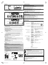
CONTROLS
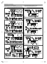
Control cover
To operate the following controls, remove the hex screws with a provided hex wrench
(2.5 mm) and detach the control cover. Attach it again after your operation.
Screw—Dia. 4 mm (
3
/16 inch) × 12 mm
(
1
/2 inch) (provided for RM-RK130)
Remote cord
(provided for
RM-RK130)
Drilled hole
Under the
dashboard, etc.
RM-RK130
POWER lamp
BASS BOOST
controller
AB
C
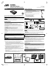
Dear Customer,
This apparatus is in conformance with the valid European directives and standards regarding
electromagnetic compatibility and electrical safety.
European representative of Victor Company of Japan, Limited is:
JVC Technical Services Europe GmbH
Postfach 10 05 04
61145 Friedberg
Germany
Hex wrench (2.5 mm)
Hex screw
Information for Users on Disposal of Old Equipment and Batteries
[European Union only]
These symbols indicate that the product and the battery with this symbol should
not be disposed as general household waste at its end-of-life.
If you wish to dispose of this product and the battery, please do so in accordance
with applicable national legislation or other rules in your country and municipality.
By disposing of this product correctly, you will help to conserve natural resources
and will help prevent potential negative effects on the environment and human
health.
Notice:
The sign Pb below the symbol for batteries indicates that this battery contains lead.
Products
Battery
EN_KSAR9004_9001D[JK]5.indd 3EN_KSAR9004_9001D[JK]5.indd 3 09.1.15 10:16:13 AM09.1.15 10:16:13 AM