


9
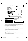
Before connecting video components
About HDMI
IMPORTANT:
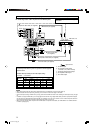
The HDMI video signals from the HDMI terminal are transmitted only through the HDMI MONITOR OUT terminal.
Therefore, if the TV is connected to the receiver through the AV IN/OUT terminal (TV) or COMPONENT VIDEO jacks (MONITOR OUT)
and a playing video component is connected to the receiver through the HDMI terminal (VIDEO (VCR) IN or DVR/DVD IN), you cannot
view the playback picture on the TV.
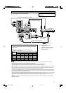
About SCART
You can enjoy pictures and sounds from playback components simply by connecting with the SCART cable.
• For an analogue decoder
To watch through or to record a scrambled program on your VCR, connect the analogue decoder to your VCR and select the
scrambled channel on your VCR.
If an appropriate terminal for the decoder connection is not equipped for your VCR, connect the decoder to your TV.
Refer also to the manuals supplied with these components.
• For T-V LINK
•You can use the T-V LINK function if you connect a T-V LINK compatible TV and VCR to this receiver with a fully wired SCART
cables. For details on T-V LINK, refer also to the manuals supplied with the TV and the VCR.
• Connect a SCART cable to EXT-2 terminal on the JVC’s T-V LINK compatible TV for the T-V LINK function.
• Some video components support the data communication like T-V LINK. For complete details, refer also to the manuals supplied with
these components.
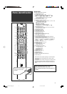
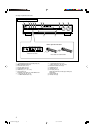
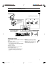
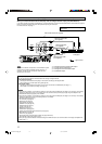
Connecting video components
Do not connect the AC power plug to the wall outlet until all connections are completed.
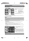
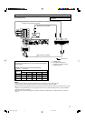
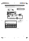
Video conversion function
This receiver can convert the video signals output from video components. The chart below shows which video signals can be converted
into which signals by video conversion.
NOTES
• HDMI and RGB signals cannot be converted into other video signals.
• With HDMI signals transmitted or input video signals converted into HDMI signals, the playback picture may be distorted when you
change the playback mode (fast-forward, rewind, or pause, for example).
To use the video conversion function, you need to make the two
settings below when you finish connecting your TV and video
components.
VIDEO OUTPUT: Select the settings according to the
connection method for your TV. See
pages 10 and 33 for details.
VIDEO INPUT: Select the settings according to the
connection method for your video
components. This setting is memorized
for each source. See pages 11 to 15 and
20 for details.
Converted video signals available vary depending on each source
component. See also page 10 to 15 for details.
Video Input Converted Video Output
CMPNT (component)
S (S-video)
C (composite)
CMPNT (component)
S (S-video)
C (composite)
HDMIHDMI
RGBRGB
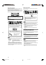
SCART Terminal Specifications : Available, –: Not available
Terminal name
TV VCR DVR/DVD
Audio L/R
Input
Composite
Video
S-video (Y/C)
–
RGB –
Audio L/R –
Output
Composite *1 *1 *1
Video
S-video (Y/C)
––
RGB ––
T-V LINK *2 *2 *2
*1 The signals input from a SCART terminal cannot be output
through the same SCART terminal.
*2 The signals for the T-V LINK function are always going
through the receiver.
CAUTION:
If you connect a sound-enhancing device such as a graphic equalizer between the source components and this receiver, the sound
output through this receiver may be distorted.
NOTES
• Composite video signals and S-video signals can be converted
into all types of signals except RGB. See above for details.
• When you record a playback picture with a DVD recorder or
VCR connected to this receiver, perform either one of the below.
– Set the video input setting (see page 20) to a setting other
than “S” to transmit composite video or RGB signals to this
receiver.
– Set “VIDEO OUTPUT” (see page 33) to “RGB/C” to transmit
S-video signals from a playback component to this receiver.
09-15RX-D701S[B]_f.p65 05.11.9, 11:32 AM9