


➔➔
➔➔➔
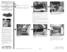
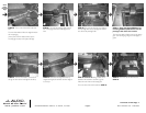
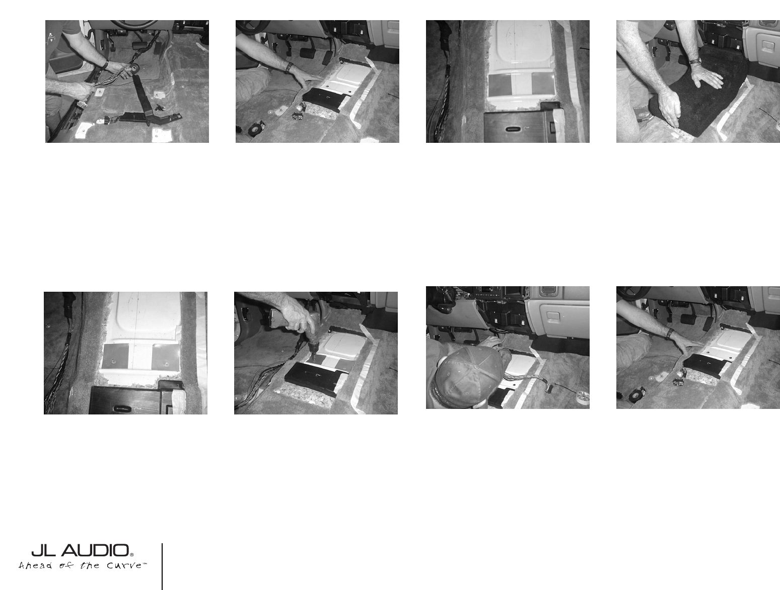
STEP 14: With the OEM carpet and the
jute(sound deadening) cut out. Position the supplied
pair of 3”x3” wax squares in place.
Make sure that the wax square is placed and with
the adhesive down and positioned as in the picture.
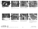
STEP 18: The wire harness from STEP 12 needs
to be rerouted over to the other side of the struc-
ture support bar under the dash.
Also at this time, run the speaker wire form the
amplifier location to the Stealthbox location.
Double check the woofer for correct functioning.
Cont.
From
Previous
Page
Continued on Next Page ➔
➔
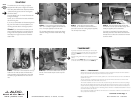
STEP 15: Thread the supplied pair of socket cup
set screws into the Stealthbox. Leaving about 1/4”
exposed.
Position the Stealthbox into the mounting location
and firmly press down.
The Stealthbox is molded to mirror the floor. It
should tuck right in.
STEP 19: With the wire harness properly tucked
under the carpet, use double sided tape(not sup-
plied) to secure the carpet to the metal floor.
If the carpet is not secured to the floor, it will bunch
up after the OEM console is reinstalled.
Remove the masking tape that outlined the OEM
console from STEP2.
➔
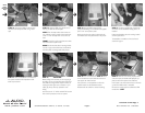
STEP 16: When the Stealthbox is removed, the
wax square should have the impressions of the
socket cup set screws.
STEP 17: *CAUTION*
Before drilling, make sure that you are not going to
be drilling into any gas lines, brake lines, transmission
lines, electrical wiring, transfer case(4x4 vehicles) or
anything else that might cause a reduction in your
weekly pay. Always wear eye protection when
drilling.
With the use of a 1/2” drill bit and drill. Drill out the
floor at the’ impressions on the wax squares.
SB-GM-BURBCNSL/10W3v2, JL AUDIO, Inc 2005
Sheet SKU#011167 3/08/2005Page 3
www.jlaudio.com
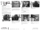
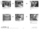
STEP 12: Remove the OEM wire harness from
the plastic track. Wrap the OEM wiring in black
tape.
STEP 13: With the OEM wiring harness out of
the way, you need to cut the carpet.
SIDES: From the tape outline of the center con
sole, measure inward to middle of the transmission
tunnel 1.5” from the tape. Mark and cut, front to
back.
FRONT: Cut left to right at the front area where
the outline starts to taper inward.
REAR: Feel for the black plastic mounting bracket.
Cut left to right at the transmission tunnel, behind
the black plastic mounting bracket.View picture.