


| Fathom IWSPage 14
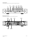
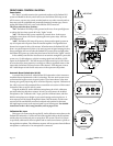
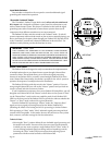
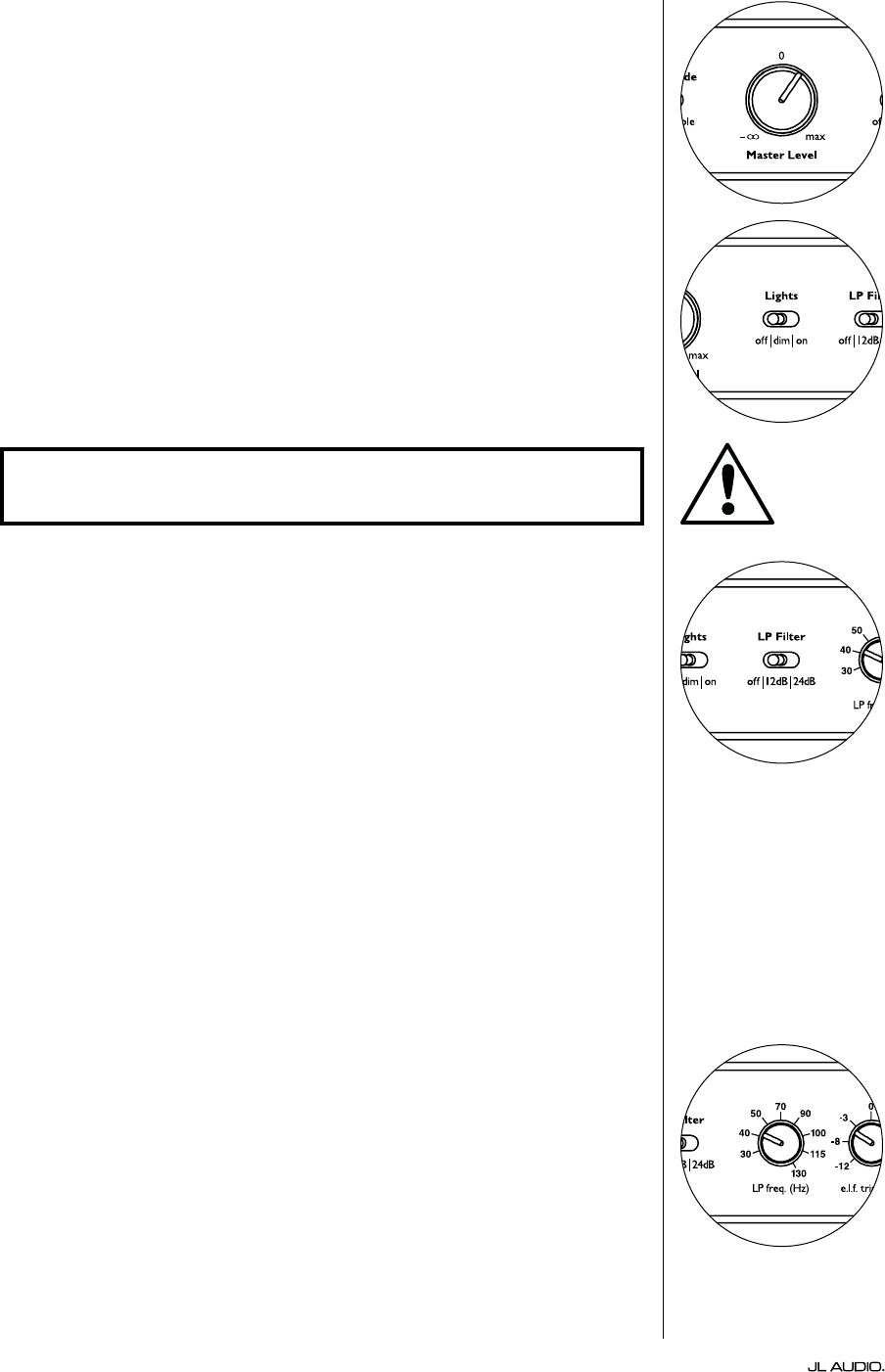
Master Level Knob
e Master Level Knob is used to control the output level of the Fathom IWS
when the Variable Level mode is selected on the front control panel.
When rotated fully counter clockwise, the Fathom IWS’s output will be fully
muted. When at the “0” or straight up position, the Variable gain level matches
the Reference level setting. When turned fully clockwise, the Fathom IWS’s
output level is 15 dB higher than the Reference setting.
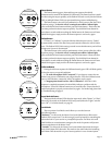
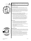
Lights
e “Lights” selector switch allows the user to select one of three indicator
light modes.
“O” turns o all of the front panel LED’s at all times.
“Dim” sets all of the front panel LEDs to a low brightness level when the
Fathom IWS is turned on.
“On” sets all of the front panel LEDs to full brightness level when the Fathom
IWS is turned on.
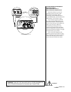
LP Filter
e Low Pass (LP) Filter selector switch determines the operating mode of the
Fathom IWS’s built-in low pass lter.
“O” defeats the low pass lter, completely removing this circuit from the
signal path.
“12 dB” sets the roll o slope of the low pass lter to a 12 dB per octave slope
(Butterworth alignment).
“24 dB” sets the roll o slope of the low pass lter to a 24 dB per octave slope
(Linkwitz-Riley alignment).
e 24 dB setting more aggressively attenuates high frequencies above the
LP Frequency setting (see below). If you are using the Fathom IWS’s built-in
low pass lter, experiment with the LP Filter slope setting to achieve the best
transition to your satellite speakers. If you prefer to use the lters and bass
management features in your receiver or preamplier, defeat the
on-board lter by selecting the “O” position.
If the Fathom IWS enclosure is placed close to the listening position, it may
be very easy to localize the sub’s output. Experiment with the low pass lter to
make the subwoofer less easy to localize.
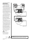
LP Freq
e Low Pass (LP) Frequency selector knob allows the user to choose the
roll-o frequency of the Fathom IWS’s internal low pass lter. e frequency is
variable between 30 Hz (full counter-clockwise) to 130 Hz (full clockwise). is
knob does not aect the input signal in any way if the LP Filter switch is set to
“O”. 80 Hz is a commonly used lter frequency and usually serves as a good
starting point for adjustments.
IMPORTANT
IMPORTANT: WHEN TROUBLESHOOTING OR CALIBRATING THE A.R.O.
FEATURE, MAKE SURE THAT THE “LIGHTS” SWITCH IS SET TO “DIM” or “ON.”