


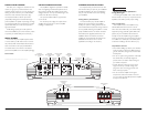
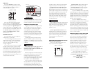
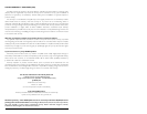
1) “Filter Mode” Control:The e2150 employs a
12dB per octave filter.This filter can be configured
into one of two filter types or defeated completely
by way of the three-position “Filter Mode” switch:
“Off”: Defeats the filter completely, allowing the full
range of frequencies present at the inputs to feed
the amplifier.This is useful for systems utilizing
outboard crossovers or requiring full-range
reproduction from the e2150.
“LP” (Low-Pass): Configures the filter to attenuate
frequencies above the selected filter frequency at a
rate of 12dB per octave. Useful for connection of
subwoofer(s) to the e2150 in a bi-amplified system.
“HP” (High-Pass): Configures the filter to attenuate
frequencies below the selected filter frequency at a
rate of 12dB per octave. Useful for connection of
coaxial or component satellite speaker systems to
the e2150 in a bi-amplified system.
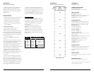
2) “Filter Freq.(Hz)”The filter frequency
markings surrounding this rotary control are for
reference purposes and are generally accurate to
within 1/3 octave or better. If you would like to
select the filter cutoff frequency with a higher level of
precision, consult the chart in Appendix B (page 11).
Tuning Hint: If you are using the e2150 to drive a
subwoofer system (“LP”mode) or a component
satellite speaker system (“HP”mode), 100 Hz is a
good baseline “Filter Freq. (Hz)” setting.After
properly adjusting the “Input Sens.”, as outlined in
Appendix A (page 10), you can fine tune the
“Filter Freq. (Hz)” control to achieve the desired
system frequency response.
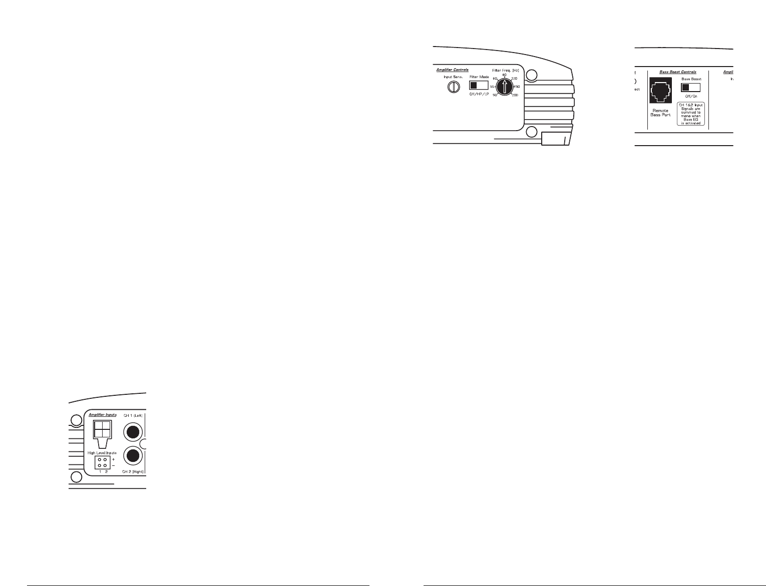
BASS BOOST CONTROLS
1) Bass Boost: This switch allows the user to
activate a 6 dB boost centered at 48 Hz.When the
“Bass Boost” is activated, the inputs to “CH 1
(Left)” and “CH 2 (Right)” are summed to create
a mono signal.The “Filter Mode” switch in the
“Channel 1 & 2” section must be in the “LP”
position for the bass boost to be functional.
2) Remote Bass Port: This port allows you to
connect an optional remote boost knob (sold
separately, JL Audio Model RBC-1) that can be
mounted in the front of the vehicle. With the
RBC-1 connected, the boost is no longer limited to
0 or +6 dB, allowing a range of 0 - 12 dB of boost
to be selected.
JL AUDIO e2150 7
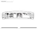
TURN-ON LEAD
The e2150 uses a conventional +12V remote
turn-on lead, typically controlled by the source unit's
remote turn-on output.The amplifier will turn on
when +12V is present at its “Remote” input and
turn off when +12V is switched off. If a source unit
does not have a dedicated remote turn-on output,
the amplifier’s turn-on lead can be connected to
+12V via a switch that derives power from an
ignition-switched circuit.
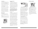
The e2150's “Remote” turn-on connector is
designed to accept 18 AWG – 12 AWG wire.To
connect the remote turn-on wire to the amplifier,
first back out the set screw on the top of the
terminal block, using the supplied 2.5 mm hex
wrench. Strip 1/2 inch (12mm) of wire and insert
the bare wire into the terminal block, seating it
firmly so that no bare wire is exposed.While
holding the wire in the terminal, tighten the set
screw firmly, taking care not to strip the head of the
screw and making sure that the wire is firmly
gripped by the set screw.
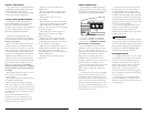
INPUT SECTION
The e2150 has one input section with two
distinct input connection options.These are:
1) A pair of traditional RCA type connections
designed to accept input from source units with line
level outputs.
2) A four-pin connector designed to accept input
from amplified sources such as factory source units
or source units not equipped with line level outputs.
AMPLIFIER CONTROLS
Input Sensitivity
This control, labeled “Input Sens.”, can be used
to match the source unit's output voltage to the
input stage of the e2150 for maximum clean
output. Rotating the control clockwise will result in
higher sensitivity (louder for a given input voltage).
Rotating the control counter-clockwise will result in
lower sensitivity (quieter for a given input voltage.)
To properly set the amplifier for maximum clean
output, please refer to Appendix A (page 10).After
using this procedure, you can then adjust the
“Input Sens.” level downward if this is required to
achieve the desired system balance.
Do not increase any “Input Sens.” setting for
any channel(s) of any amplifier in the system
beyond the maximum level established during the
procedure outlined in Appendix A (page 10).
Doing so will result in audible distortion and
possible speaker damage.
Filter Controls
Most speakers are not designed to reproduce
the full range of frequencies audible by the human
ear. For this reason, most speaker systems are
comprised of multiple speakers, each dedicated to
reproducing a specific frequency range. Filters are
used to select which frequency range is sent to
each section of a speaker system.The division of
frequency ranges to different speakers can be
done with passive filters (coils and/or capacitors
between the amplifier outputs and the speakers),
which are acceptable and commonly used for
filtering between mids and tweeters. Filtering
between subwoofer systems and satellite speaker
systems is best done with active filters, which cut
off frequency content at the input to the amplifier.
Active filters are more stable than passive filters
and do not introduce extraneous resistance,
which can degrade subwoofer performance.
The active filter built into the e2150 can be used
to eliminate potentially harmful and/or undesired
frequencies from making their way through the
amplifier section to the speaker(s).This serves to
improve tonal balance and to avoid distortion and
possible speaker failure. Correct use of this filter can
substantially increase the longevity and fidelity of
your audio system.
6 JL AUDIO e2150