


which are acceptable and commonly used for
filtering between mids and tweeters. Filtering
between subwoofer systems and satellite speaker
systems is best done with active filters, which cut
off frequency content at the input to the amplifier.
Active filters are more stable than passive filters
and do not introduce extraneous resistance,
which can degrade subwoofer performance.
The active filter built into the e1800D can be
used to eliminate potentially harmful and/or
undesired frequencies from making their way
through the amplifier section to the subwoofer(s).
This serves to improve tonal balance and to avoid
distortion and possible speaker failure. Correct use
of this filter can substantially increase the longevity
and fidelity of your audio system.
The e1800D employs a sophisticated, variable,
low-pass active filter for its internal channel.This
feature is designed to attenuate frequencies above its
filter frequency, so that the system's subwoofers do
not reproduce any audible midrange content.
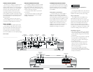
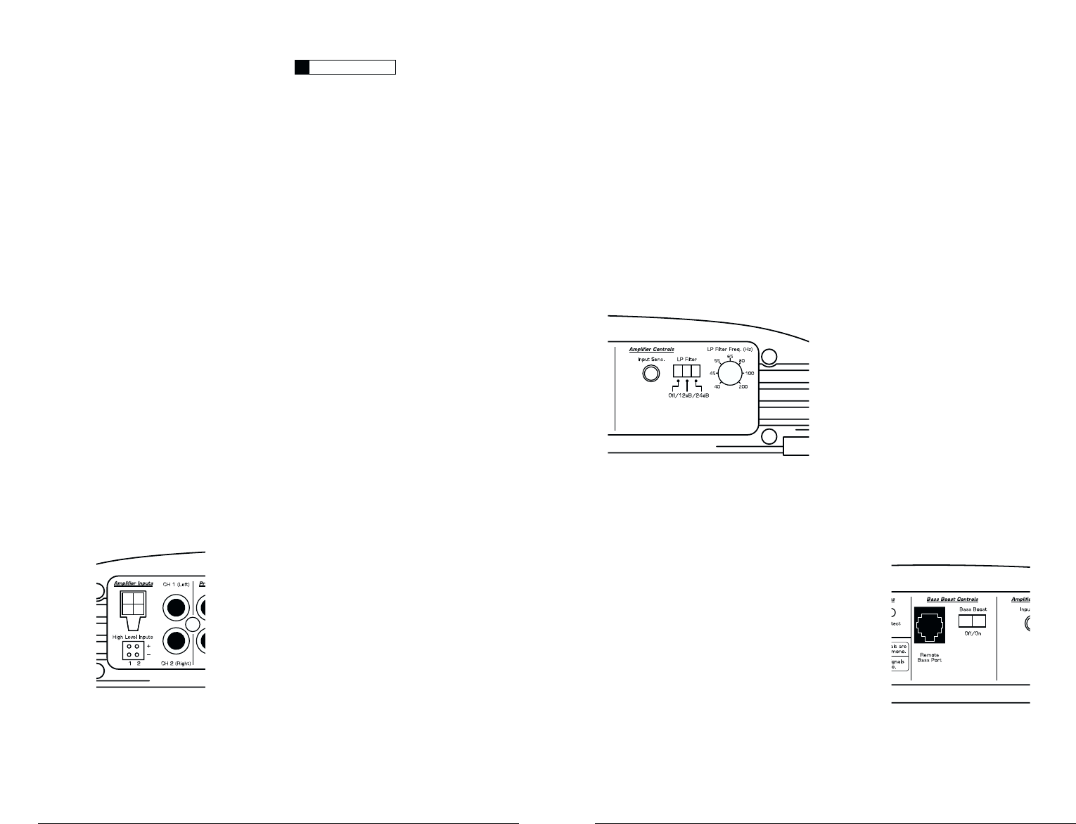
1) Filter Operation:The low-pass filter in the
e1800D is fully variable between 40 Hz and 200 Hz
via the “Filter Freq.” control knob and features the
ability to select between a moderate “12dB” per
octave or a steep “24dB” per octave slope via the
“Mode/Slope” switch.
Depending on the subwoofer system and the
vehicle, different slopes may be required to produce
a smooth transition to the mid-bass speakers in the
system. Experiment to find the slope which best
matches the acoustic requirements of your system.
Hint: A trunk mounted sub whose output has to
"fight" through a rear deck or a back seat often
benefits from the 12 dB/octave slope which lets
more upper bass content pass through.A sub that
fires directly into the listening environment is more
likely to benefit from a 24 dB/octave slope.
The above hint is not “set-in-stone”…
You should always listen to the system carefully to
determine the best choice as vehicle acoustics and
other factors play a big role in choosing the most
appropriate filter slope.
2) Precise Frequency Selection:The filter
frequency markings on the front panel of the
amplifier are for reference purposes and are
generally accurate to within 1/3 octave or better.
If you would like to select the filter frequency with
a higher level of precision, consult Appendix B
(page 11) of this manual.This chart gives you a
more accurate frequency for each of the forty
detented positions of the frequency selection
control.This method can be very useful if the
amplifier is mounted in a location where you can’t
see the front panel markings easily.
3) Defeating the Amplifier Filter:The Low-
Pass filter can also be defeated completely, by
switching the “Mode/Slope” switch to the “Off”
position.This is useful if you are using an external
active crossover in the system. Keep in mind that
turning the internal crossover off also defeats the
“Advanced Bass Control” section processing
(see page 9 for details).With the internal
crossover turned off, the e1800D’s upper
frequency response limit is 250 Hz, due to its
bass-specific Class D design.
BASS BOOST CONTROLS
1) Bass Boost: This switch allows the user to
activate a 6 dB boost centered at 48 Hz.The “Filter
Mode” switch in the “Channel 1 & 2” section must
be in the “LP” position for the bass boost to
be functional.
JL AUDIO e1800D 7
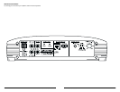
TURN-ON LEAD
The e1800D uses a conventional +12V remote
turn-on lead, typically controlled by the source unit's
remote turn-on output.The amplifier will turn on
when +12V is present at its “Remote” input and
turn off when +12V is switched off. If a source unit
does not have a dedicated remote turn-on output,
the amplifier’s turn-on lead can be connected to
+12V via a switch that derives power from an
ignition-switched circuit.
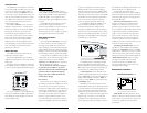
The e1800D's “Remote” turn-on connector is
designed to accept 18 AWG – 12 AWG wire.To
connect the remote turn-on wire to the amplifier,
first back out the set screw on the top of the
terminal block, using the supplied 2.5 mm hex
wrench. Strip 1/2 inch (12mm) of wire and insert
the bare wire into the terminal block, seating it
firmly so that no bare wire is exposed.While
holding the wire in the terminal, tighten the set
screw firmly, taking care not to strip the head of the
screw and making sure that the wire is firmly
gripped by the set screw.
INPUT SECTION
The e1800D has one input section with two
distinct input connection options.
1) A pair of traditional RCA type connections
designed to accept input from source units with line
level outputs.
2) A four-pin connector designed to accept input
from amplified sources such as factory source units
or source units not equipped with line level outputs.
You may run a stereo or a mono signal into the
inputs of the amplifier.The amplifier's input section
automatically sums stereo signals to mono for the
internal amplifier section.
If you plan to use the “Pre-Outs” to feed a
stereo amplifier, you must connect a stereo signal to
the input of the amplifier. A mono signal into the
amplifier will result in a mono signal out of the
preamp output. (It's a great amplifier, but it doesn't
do magic).
The amplifier will operate with only one input
connection (left or right), but will require an
increase in input sensitivity to overcome the loss of
signal. If a mono input signal is to be run, we
recommend that you use a “Y-adaptor” to split the
mono signal into both inputs of the amplifier.
AMPLIFIER CONTROLS
Input Sensitivity
This control, labeled “Input Sens.”, can be used
to match the source unit's output voltage to the
input stage of the e1800D for maximum clean
output. Rotating the control clockwise will result in
higher sensitivity (louder for a given input voltage).
Rotating the control counter-clockwise will result in
lower sensitivity (quieter for a given input voltage.)
To properly set the amplifier for maximum clean
output, please refer to Appendix A (page 10).After
using this procedure, you can then adjust the
“Input Sens.” level downward if this is required to
achieve the desired system balance.
Do not increase any “Input Sens.” setting for
any channel(s) of any amplifier in the system
beyond the maximum level established during the
procedure outlined in Appendix A (page 10).
Doing so will result in audible distortion and
possible speaker damage.
Filter Controls
Most speakers are not designed to reproduce
the full range of frequencies audible by the human
ear. For this reason, most speaker systems are
comprised of multiple speakers, each dedicated to
reproducing a specific frequency range. Filters are
used to select which frequency range is sent to
each section of a speaker system.The division of
frequency ranges to different speakers can be
done with passive filters (coils and/or capacitors
between the amplifier outputs and the speakers),
IMPORTANT
!
6 JL AUDIO e1800D