


APPENDIX B:
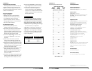
Precise Frequency Selection Chart
“FILTER FREQ” AMP FILTER
Detent Panel Actual
Number Marking Freq.
Full counter-clockwise: 53
01 ............................53
02 ...........“50”............53
03 ............................53
04 ............................54
05 ............................54
06 ............................55
07 ............................55
08 ...........“55”............56
09 ............................56
10 ............................57
11 ............................58
12 ............................59
13 ............................62
14 ...........“60”............65
15 ............................65
16 ............................66
17 ............................70
18 ............................73
19 ............................77
20 ...........“80”............81
21 ............................84
22 ............................88
23 ............................94
24 ...........................101
25 ...........................104
26 ..........“120” ..........115
27 ...........................118
28 ...........................128
29 ...........................137
30 ...........................146
31 ...........................164
32 ..........“150” ..........177
33 ...........................193
34 ...........................197
35 ...........................209
36 ...........................213
37 ...........................216
38 ..........“200” ..........218
39 ...........................225
Full-clockwise: 225
APPENDIX C:
G1300 Specifications
General Specifications:
Recommended Fuse Value: 30A
Recommended Fuse Type: AGU, AFS or MaxiFuse™
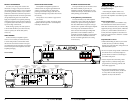
Input Sections:
No. of Inputs: One Stereo Pair
Input Type: Differential-balanced with RCA jack inputs
Input Range: Switchable from 200mV - 2V RMS to
800mV - 8V RMS
Amplifier Section:
Amplifier Topology: Class A/B with patented Absolute
Symmetry™ dual N-Channel MOSFET output design
Power Supply: Unregulated MOSFET switching type
Rated Power @ 14.4V with less than
1% THD + Noise (20Hz - 20 kHz):
150W RMS x 1 @ 4 ohms, 300W RMS x 1 @ 2 ohms
Rated Power at 12.5 V with less than
1% THD+Noise (20Hz - 2 kHz):
120W RMS x 1 @ 4 ohms, 220W RMS x 1 @ 2 ohms
Signal to Noise Ratio: >104 dB referred to rated power
(A-weighted, 20 Hz-20 kHz noise bandwidth)
Frequency Response: 10 Hz - 25 kHz (+0, -1dB)
Damping Factor: >200 @ 4 ohms/50 Hz,
>100 @ 2 ohms/50 Hz
Slew Rate: ± 22V/µs
Amplifier Filter:
Filter Type: State-variable, 12dB/octave Butterworth with
continuously variable cutoff frequency selection from
50-200 Hz. Configurable as Low-Pass or High-Pass.
Defeatable.
Preamp Output:
Buffered pass-through type.
Dimensions(LxWxH):
9.8" x 9.25" x 2.50" (250mm x 235mm x 63.5mm)
APPENDIX A:
Input Sensitivity Level Setting
Following the directions below will allow the
installer to adjust the input sensitivity of each
amplifier channel pair simply and easily in just a
few minutes using equipment which is commonly
available in installation bays.
Necessary Equipment
• Digital AC Voltmeter
• CD with a sine-wave test tone recorded at
0 dB reference level in the frequency range
to be amplified for that set of channels
(50 Hz for subwoofer channels, 1 kHz for a
midrange application). Do not use attenuated
test tones (-10 dB, -20 dB, etc.).
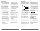
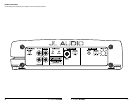
The Nine-Step Procedure
1) Disconnect the speaker(s) from the
amplifier’s speaker output connectors.
2) Turn off all processing (bass/treble, loudness,
EQ, etc.) on the source unit, processors (if
used) and amplifier. Set fader control to center
position and subwoofer level control to 3/4 of
maximum (if used to feed the G1300).
3) Switch the “Input Voltage” switch to “Low”
and turn the “Input Sens.” control all the
way down.
4) Set the source unit volume to 3/4 of full
volume. This will allow for reasonable gain
overlap with moderate clipping at full volume.
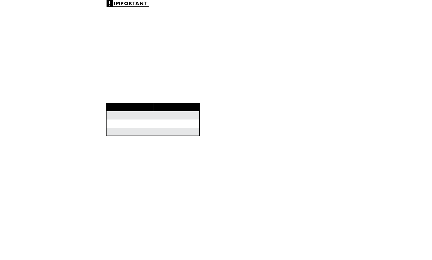
5) Using the chart on this page, determine the target
voltage for input sensitivity adjustment according
to the nominal impedance of the speaker system
connected to the amplifier outputs.
6) Verify that you have disconnected the speakers
before proceeding. Play a track with an
appropriate sine wave (within the frequency
range to be amplified by the G1300) at 3/4
source unit volume.
7) Connect the AC voltmeter to the speaker output
connectors of the amplifier. Make sure you test
the voltage at the correct connectors (+ and –).
8) Increase the “Input Sens.” control until the
target voltage is observed with the voltmeter.
9) Once you have adjusted the G1300 to its
maximum low-distortion output level,
reconnect the speaker(s). The “Input Sens.”
controls can now be adjusted downward if the
amplifier requires attenuation to achieve the
desired system balance.
Do not increase any “Input Sens.” setting for
any amplifier channel or channel pair in the
system beyond the maximum level established
during this procedure. Doing so will result in
audible distortion and possible speaker damage.
It will be necessary to re-adjust the
“Input Sens.” for the affected channels if any
equalizer boost is activated after setting the
“Input Sens.” with this procedure. This applies
to any EQ boost circuit, including source unit
tone controls or EQ circuits. EQ cuts will not
require re-adjustment.
Nom. Impedance Target AC Voltage
4 24.5 V
3 24.5 V
2 24.5 V
Due to ongoing product development, all specifications are subject to
change without notice.
12 JL AUDIO G1300 JL AUDIO G1300 13