


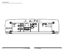
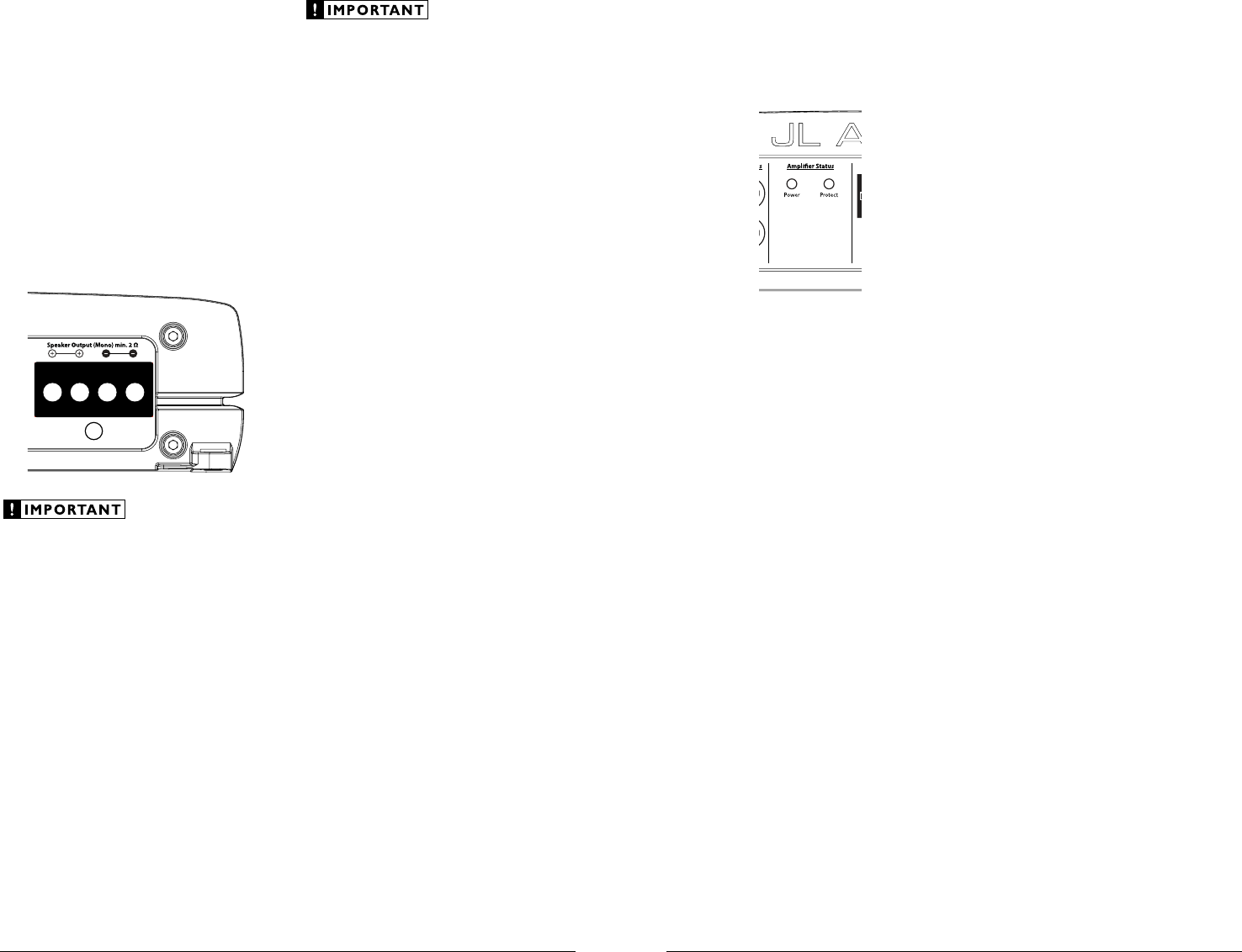
AMPLIFIER STATUS INDICATOR LIGHTS &
PROTECTION CIRCUITRY
There are two status indicator lights on the
input / control end of the amplifier.
1) “Power” (Green): lights to indicate that the
amplifier is turned on and operating normally.
2) “Protect” (Red): Indicates that the amplifier
protection circuitry has been activated to
prevent product failure due to a short-circuit
or a dangerously low impedance connected
to the amplifier output(s). Connecting the
speaker outputs to an impedance lower than
2 ohms stereo (4 ohms bridged) will cause
this protection mode to activate. When this
protection mode is activated, the amplifier will
reduce it maximum power output to protect its
circuitry, which will manifest itself as increased
distortion. When the problem is corrected, the
amplifier will return to normal operation.
Advanced Rollback Thermal protection
Unlike conventional thermal protection
systems, which shut down an amplifier when it
overheats, this system protects the amplifier by
gradually reducing power output if the amplifier’s
safe operating temperature is exceeded. The
amplifier will continue to operate and return
to normal power output once its temperature
returns to a normal range.
Low-Voltage protection:
If the car’s supply voltage drops below 10
volts, the entire amplifier will shut itself off to
protect its internal circuitry. The green “Power”
indicator will turn off when this occurs. The
amplifier will turn back on when voltage climbs
back above 10 volts. This may happen in a rapid
cycle when bass-heavy program material causes
a weak charging system to dip below 10 volts
momentarily. If this is happening in your system,
turn your audio system off and have your power
wiring, ground connections and charging
system inspected.
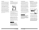
SERVICING YOUR JL AUDIO AMPLIFIER
If your amplifier fails or malfunctions, please
return it to your authorized JL Audio dealer so
that it may be sent in to JL Audio for service.
There are no user serviceable parts or fuses inside
the amplifier. The unique nature of the circuitry
in the JL Audio amplifiers requires specifically
trained service personnel. Do not attempt
to service the amplifier yourself or through
unauthorized repair facilities. This will not only
void the warranty, but may result in the creation
of more problems within the amplifier.
If you have any questions about the installation or
setup of the amplifier not covered in this manual,
please contact your dealer or technical support.
JL Audio Technical Support:
(9 5 4) 4 43 -110 0
9:00 AM – 5:30 PM (Eastern Time Zone)
Monday - Friday
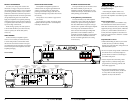
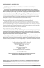
SPEAKER OUTPUTS
The G1300’s speaker outputs are designed to
accept 8 AWG - 16 AWG wire.
The G1300 is designed to deliver power into
speaker loads equal to or greater than 2 ohms.
To connect the speaker wires to the amplifier,
first back out the set screws own the top of the
terminal block, using the supplied 2.5 mm hex
wrench. Strip 1/2 inch (12 mm) of insulation from
the end of each wire and insert the bare wire into
the terminal block, seating it firmly so that no
bare wire is exposed. While holding the wire in
place, tighten the set screw firmly, taking care not
to strip the head of the screw.
Speaker loads below 2 ohms nominal are not
recommended and may cause the amplifier
to initiate a protection mode which reduces
power output.
You will notice that there are two “+” positive
connections and two “–” negative connections.
This is to facilitate multiple speaker wiring.
The two positive and two negative connections
are connected in parallel inside the amplifier.
Connecting two speakers, each to one set of
positive and negative terminals, will result in a
parallel speaker connection. If only connecting
one pair of speaker wires, it is not necessary to
use both sets of connections.
Do not attempt to “bridge” the outputs of this
amplifier with the outputs of a second amplifier,
including an identical one.
10 JL AUDIO G1300 JL AUDIO G1300 11