


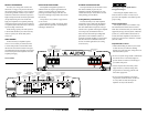

INPUT VOLTAGE RANGE:
A wide range of signal input voltages can be
accommodated by the G1300’s input section
(200mV – 8V). This wide range is split up into
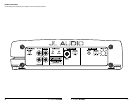
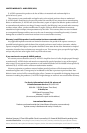
two sub-ranges, accessible via a switch located to
the left of the Input Connectors.
The “Low” position on the “Input Voltage”
switch selects an input sensitivity range between
200mV and 2V. This means that the “Input
Sens.” rotary control will operate within that
voltage window. If you are using an aftermarket
source unit or an OEM interface processor with
conventional preamp-level outputs, this is most
likely the position that you will use.
The “High” position on the “Input Voltage”
switch selects an input sensitivity range between
800mV and 8V. This is useful for certain high-
output preamp level signals as well as speaker-level
output from source units and small amplifiers.
To use speaker-level sources, splice the speaker
output wires of the source unit or small amplifier
onto a pair of RCA plugs. No line output
converter is needed in most cases.
The output of the amplifier will decrease for
a given input voltage when the “Input Range”
switch is placed in the “High” position.
Conversely, the output will be higher with the
switch in the “Low” position. While this may
sound counter-intuitive, it is consistent with
the descriptions above.
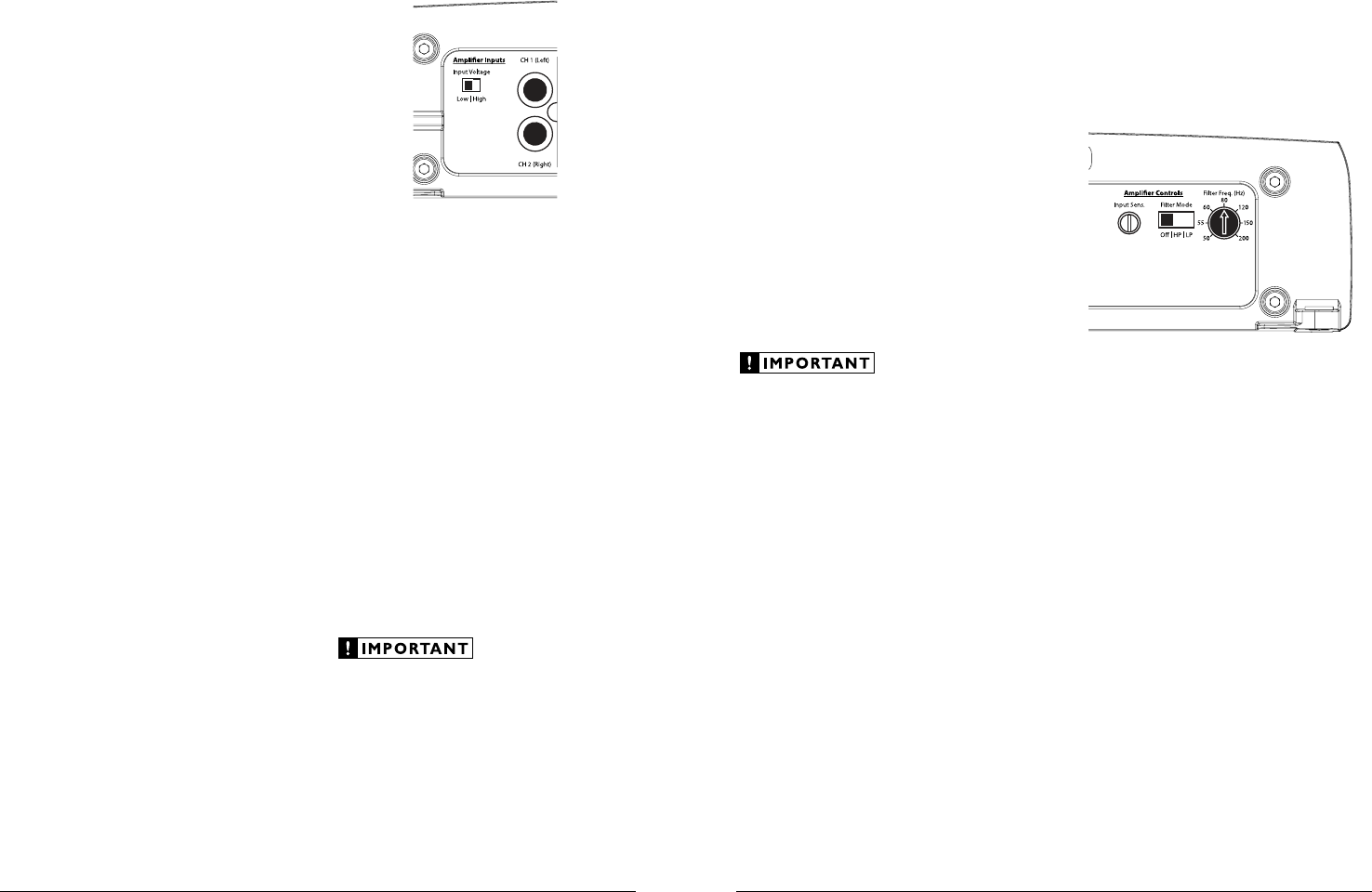
AMPLIFIER CONTROLS
1) “Input Sens.”: Once the appropriate “Input
Voltage” range has been selected, the control
labeled “Input Sens.” located in the “Amplifier
Controls” section can be used to match the
source unit’s output voltage to the input
stage of the amplifier for maximum clean
output. Rotating the control clockwise will
result in higher sensitivity (louder for a given
input voltage). Rotating the control counter-
clockwise will result in lower sensitivity
(quieter for a given input voltage.)
To properly set the amplifier for maximum
clean output, please refer to Appendix A (page
12). After using this procedure, you can then
adjust the “Input Sens.” level downward if this is
required to achieve the desired system balance.
Do not increase any “Input Sens.” setting
for any channel(s) of any amplifier in the
system beyond the maximum level established
during the procedure outlined in Appendix
A (page 12). Doing so will result in audible
distortion and possible speaker damage.
TURNON LEAD
The G1300 uses a conventional +12V remote
turn-on lead, typically controlled by the source
unit’s remote turn-on output. The amplifier will
turn on when +12V is present at its “Remote”
input and turn off when +12V is switched off. If
a source unit does not have a dedicated remote
turn-on output, the amplifier’s turn-on lead can
be connected to +12V via a switch that derives
power from an ignition-switched circuit.
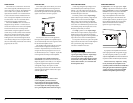
The G1300’s “Remote” turn-on connector is
designed to accept 18 AWG – 12 AWG wire. To
connect the remote turn-on wire to the amplifier,
first back out the set screw on the top of the
terminal block, using the supplied 2.5 mm hex
wrench. Strip 1/2 inch (12mm) of wire and insert
the bare wire into the terminal block, seating it
firmly so that no bare wire is exposed. While
holding the wire in the terminal, tighten the set
screw firmly, taking care not to strip the head of
the screw and making sure that the wire is firmly
gripped by the set screw.
INPUT SECTION
The G1300’s input section allows you to send
signal to the amplifier section through the use
of two differential-balanced inputs, one for the
left channel signal and one for the right channel
signal. Connection is via RCA-type jacks.
You may run a stereo or a mono signal into
the inputs of the amplifier. The amplifier’s input
section automatically sums stereo signals to mono
for the internal amplifier section.
The amplifier will operate with only one input
connection (left or right), but will require an
increase in input sensitivity to overcome the loss
of signal. If a mono input signal is to be run, we
recommend that you use a “Y-adaptor” to split the
mono signal into both inputs of the amplifier.
Left Channel Only or Right Channel Only
Information: If you wish to send a Left-only or
Right-only signal to the G1300, use a “Y-Adaptor”
to split the single channel signal into both left
and right RCA inputs. This option is useful
when using one G1300 to drive the left channel
speakers only and another G1300 to drive right
channel speakers only.
If you plan to use the “Pre-Outs” to feed
a stereo amplifier, you must connect a
stereo signal to the input of the amplifier.
A mono signal into the amplifier will result
in a mono signal out of the preamp output.
(It’s a great amplifier, but it doesn't do magic).
6 JL AUDIO G1300 JL AUDIO G1300 7