


4
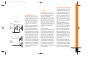
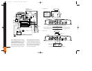
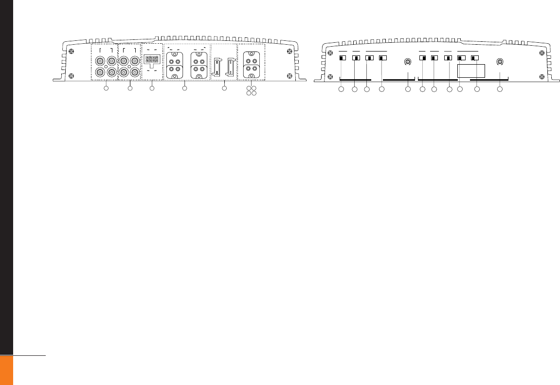
13. Mode Switches – These switches are
used to set the input mode for both pre-
amp and speaker-level inputs. Set the
switch to ST(ereo) for normal operation
on the group using individual left and
right inputs. Set this switch to R to drive
both the left and right outputs with only a
single input on the right jack. Set the
switch to L
+R to sum the left and right
inputs for a mono output on the group.
These switches do not affect the preamp
ouputs.
14. Bass EQ Switch – These switches acti-
vate a built-in Bass Boost circuit used to
increase low-bass output on the selected
group. These switches do not affect the
preamp outputs.
15. Group 2 Input Switch – This switch is
used to select which inputs will drive
Group 2 of the amplifier. Put the switch in
position “GR 1” to allow Group 2 to be
driven by the Group 1 inputs. Put the
switch in the “GR 2” position to drive
Group 2 with the Group 2 inputs.
Power Indicator LED (on amp chassis
top) – LED steadily illuminates for normal
operation. LED blinks when protection
circuitry or muting is engaged.
2.2 Controls and Connectors
1. Preamp-Level Input Connector – Use
these connectors for line-level (preamp)
inputs to the amplifier.
2. Preamp-Level Output Connector – Use
these outputs to send signal to additional
amplifiers.
3. Speaker-Level Input Connector – Use
this connector for speaker-level input sig-
nals. A wire harness is supplied for use
with this connector. This input also
includes JBL’s Common Sense input cir-
cuitry which turns the amplifier on as
soon as the high-powered head unit con-
nected to this input is turned on.
4. Speaker Output Connectors – Connect
speaker wiring to these connectors. See
wiring directions for more information.
5., 6., 7., 8. Power Connector –
Connection for power wires REM IN/OUT
and Mute. See wiring directions for infor-
mation on proper connections.
9. Fuses – GTQ240: 30A ATC type.
GTQ360: 2 x 30A ATC type.
10. Gain Controls – Use these controls to
adjust the gain of the amplifier channel
group. See the “Adjusting the Gain” sec-
tion for tips on proper setup.
11. Preamp Crossover Switches – These
switches control the built-in crossovers
that are directed to the preamp-output
connectors. Set the switch to F (flat) for
full-band operation for that group. Set the
switch to L (low) to activate the low-pass
filter on the pre-amp output group (for
subwoofer use or to use in conjunction
with a high-pass filtered input signal to
create a band-pass crossover for a
midrange or midbass driver). Set the
switch to High-Pass to activate the high-
pass filter for use with satellite speakers
or tweeters on the pre-amp output group.
12. Speaker Crossover Switches – These
switches control the built-in crossovers
that are connected to each group's power
amplifier circuitry. Set the switch to F
(flat) for full band operation on a group.
Set this switch to L (low) to activate the
low-pass filter on the selected amplifier
group for subwoofer use or to use in con-
junction with a high-pass filtered input
signal to create a band-pass crossover
(for a midrange or midbass driver). Set
the switch to H (high) to activate the high-
pass filter for use with satellite speakers
or tweeters on an amplifier group.
30A
30A
3
2
1
4
9
87
65
GR1
R GR1 L
LINE LEVEL
INPUT
SPEAKER LEVEL INPUTS SPEAKER OUTPUTS (BRIDGED: R
+
TOL
–
)
POWER
GR2 GR1 GR2
BATT(+)
GND
MUTE
FUSE
30A
FUSE
30A
REM
IN/OUT
L
+– –+
+– –+ + +
––––
R
PREAMP
OUTPUTS
R GR2 L
L GR1 R
++
L GR2 R
15
14
13
13
12
12
11
11
10 10
14
BASS EQ
OFF ON
BASS EQ
OFF ON
CROSSOVER
SPEAKER PREAMP
MODE INPUT MODE
R ST L+R
R ST L+RL
MIN MAX
GAIN
MIN MAX
GAIN
L
FFHH
L
GR2GR1
L
FFHH
GROUP 1
GROUP 2
CROSSOVER DESIGNATIONS
F = FLAT (BYPASS)
L = LOW PASS
H = HIGH PASS
CROSSOVER
SPEAKER PREAMP
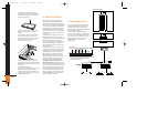
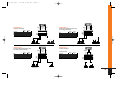
3. System Design Using
the GTQ360 and GTQ240
3.1 Speaker Requirements
When used in the non-bridged mode, a
group-channel of the GTQ360 or GTQ240
can easily drive two 2-ohm speaker loads.
When only one speaker is connected to
the left and right outputs of a group, virtu-
ally any conventional speaker may be
used. Although the amplifier will not be
damaged, load impedances lower than 2
ohms will eventually cause the amplifier
to overheat, activating the protection cir-
cuits and causing the unit to shut off until
it cools down sufficiently.
When a group is in bridged mode, the
combined impedance of the speaker (or
speakers) connected to the bridged chan-
nels should be at least 4 ohms. Sustained
operation of the unit in bridged mode
with less than 4 ohms will likely cause
overheating.
The GTQ360 or GTQ240 must not be used
with speakers that have either one of
their input terminals wired to the frame
of the speaker or to the chassis of the
vehicle.
GTQ 360 new 7/17/98 10:44 AM Page 4