


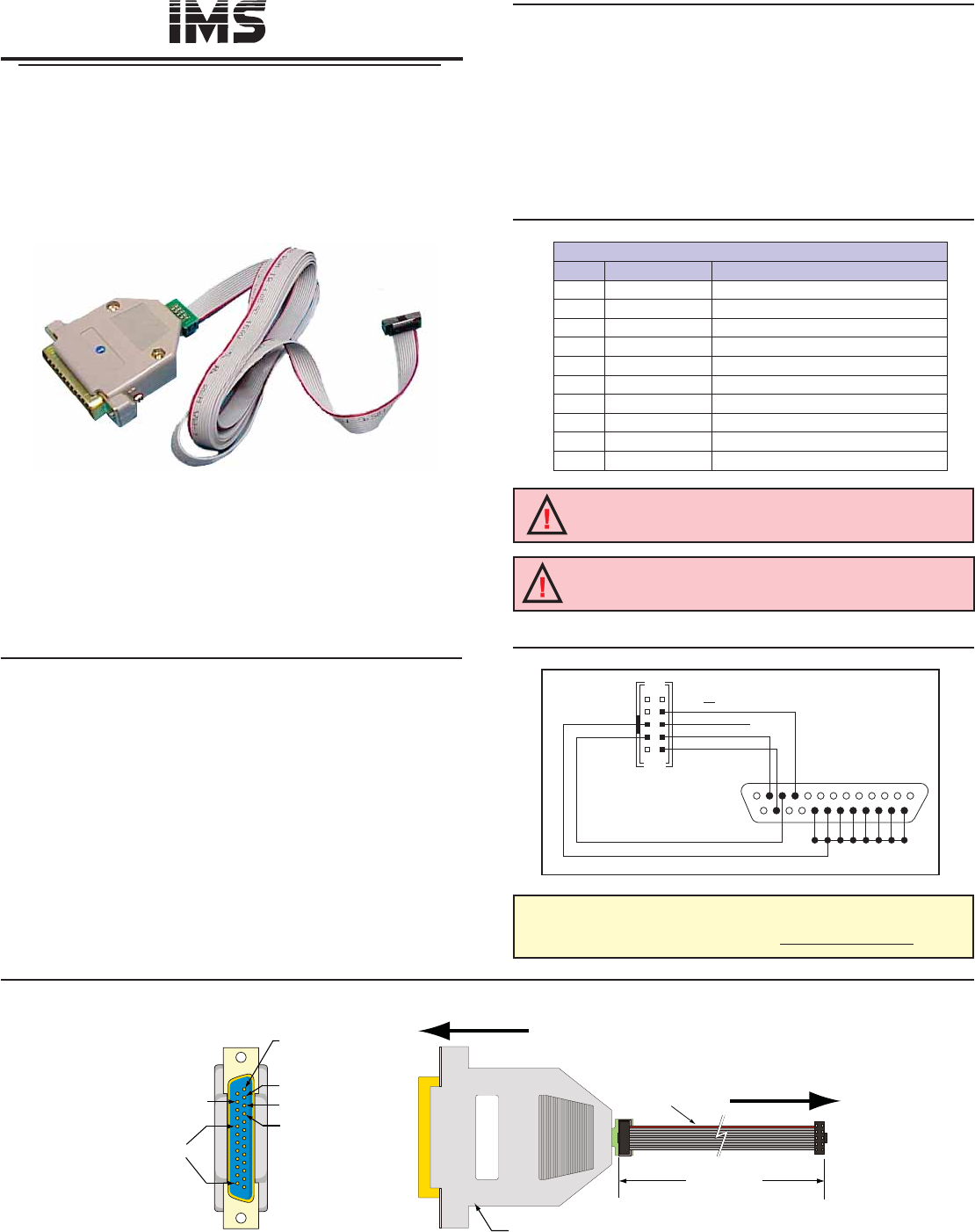
Pin 1
Pin 2 - SPI Clock
Pin 3 - MOSI
Pin 4 - SPI Chip Select
Pin 15 - MISO
Pins 18-25
Ground
To Customer PC
Parallel/SPI Port
To 10 Pin Header
Cable Length
6 Feet (1.8 M)
Red Wire
# 1 Pin
Standard DB-25
Parallel/SPI Connector
intelligent motion systems, inc.
Excellence in Motion
TM
370 N. MAIN ST., PO BOX 457, MARLBOROUGH, CT 06447
PH: (860) 295-6102, FAX: (860) 295-6107
Internet: www.imshome.com, E-Mail: info@imshome.com
TM
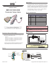
MD-CC100-000
Parameter Setup Cable
The MD-CC100-000 Parameter Setup Cable is de signed to be
used with the following IMS products:
MDrive14*
MDrive17 Microstepping* and Speed Control Versions
MDrive23 Microstepping* and Speed Control Versions
MDrive34 Microstepping and Speed Control Versions
USC-48-2 Universal Speed Control
* The MDrive14, MDrive17C and MDrive23C are equipped with C Connector and
require an Adapter Cable to interface with the MD-CC100-000. The optional
Prototype Development Cable is also recommended for these products.
23
4
15
19
PIN 4 - CS
GND - PIN 5
MOSI - PIN 7
PIN8-CLOCK
PIN 6 - +5VDC OUT
PIN 10 - MISO
10 Pin Header
P2
Ground
DB-25 Standard
PC Parallel/SPI Port
Parameter Setup Cable Usage
SPI Interface
SPI Pin Assignments
Description
The MD-CC100-000 Parameter Setup Cable eliminates
the need for the user to wire communications to the IMS
product. In clud ed in this cable is built-in logic level shifting
cir cuit ry to ac com mo date the 3.3v ports on some PCs.
This cable plugs in easily to con nect a stan dard DB-25
PC Parallel/SPI port to the 10 pin header.
For More Information:
See each product’s complete manual
on the IMS Product CD or at www.imshome.com
Copyright © 2003–2004 Intelligent Motion Systems, Inc.Revision 102104
Details
WARNING! The +5VDC output is used for the setup cable
ONLY! This output is not designed to power external devices!
10 Pin Header
Pin # Pin Name Description
1 N/C No Connect
2 N/C No Connect
3 N/C No Connect
4 CS Chip Select
5 GND Communications Ground
6 +5VDC +5VDC Output (See Warning Below)
7 MOSI Master Out – Slave In
8 CLK Clock
9 N/C No Connect
10 MISO Master In – Slave Out
WARNING! DO NOT connect or disconnect the MD-CC100-000
Parameter Setup Cable while power is applied!