


6
2
PANEL DESCRIPTION
2
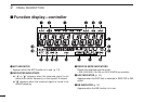
yDSP INDICATOR (p. 43)
Appears when the DSP digital filter function is in use.
• The DSP function requires an optional UT-106 installation.
uFREQUENCY READOUT
Shows the operating frequency, channel names, set mode
contents, etc.
• Frequency decimal point blinks while scanning. (p. 26)
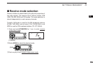
iMEMORY INDICATOR (p. 16)
Appears when memory mode
is selected.
oAUTO POWER-OFF INDICATOR (p. 36)
Appears while the auto power OFF function is activated.
!0PRIORITY INDICATOR (p. 30)
Appears while the priority watch is activated; blinks while
the watch is paused.
!1MEMORY CHANNEL NUMBER INDICATORS
➥ Shows the selected memory channel number. (p. 16)
➥ Shows the selected bank initial. (p. 23)
➥ “L” appears when the lock function is activated. (p. 11)
!2SKIP INDICATORS (p. 28)
➥ “~” appears when the displayed memory channel is
specified as a skip channel.
➥ “
P
~” appears when the displayed frequency is speci-
fied as a program skip frequency.
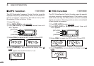
!3VSC INDICATOR (p. 13)
Appears when the VSC function is in use.
!4TONE SQUELCH INDICATOR (p. 33)
Appears when the tone squelch function is in use.
!5POCKET BEEP INDICATOR (p. 32)
Appears with “ ” or “ ” while the pocket beep function
(with CTCSS or DTCS) is in use.
!6DTCS SQUELCH INDICATOR (p. 33)
Appears while the DTCS squelch function is in use.
!7ATT INDICATOR (p. 12)
Appears when the ATT function is in use.
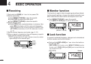
!8BUSY INDICATOR
➥ Appears when a signal is being received or the squelch
is open. (p. 11)
➥ Blinks while the monitor function is in use. (p. 11)
!9S-METER INDICATORS
Shows the relative signal strength while receiving signals.
(p. 11)